Announcement

Collapse
No announcement yet.

Acer v3-571 / la-7912p / Assistance on the circuit

Collapse
X
 
  • Filter
  • Time
  • Show
Clear All
new posts

    Acer v3-571 / la-7912p / Assistance on the circuit

    Greetings from Brazil.
    I request assistance to understand the circuit operation of this board.
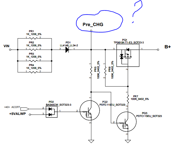
    Does anyone know how to tell the circuit on page 45 of the diagram? La-7912p. What does the Pre_CHG line do?


    Attached Files
    Last edited by SMDFlea; 07-28-2020, 09:37 AM. Reason: translate.google.com

    #2
    Re: Acer v3-571 / la-7912p / Auxilio sobre o circuito

    hi, i think pre_chg is pre charge chircuit. it is first mosfet and after that B+ goes to charging ic circuit and to a second mosfet like all other notebook.


    edit getting whole schematic looks like a circuit to control if charger is present or not.

    this notebook has another circuit for battery. there is also a battery-on power button that need to be pressed by notebook undercover to enable the battery voltage.

    both batt+ and dcin goes to vin voltage; or from charger or from battery. and tht circuit tell notebook if charger is present or not.
    Last edited by dellxps15; 07-30-2020, 04:21 PM.

    Comment


      #3
      Re: Acer v3-571 / la-7912p / Assistance on the circuit

      The "Pre_CHG" label itself only exists on that schematic because there is a link to a component on another page.

      But a pre-charge circuit, like the one above, is designed to provide a high resistance path from the power jack to the main power rail (B+) when the AC adapter is first plugged in. This makes sure the voltage doesn't rise so sharply that it would cause stress/damage to components on that rail. Also, all the capacitors on B+ will draw a lot of current (inrush current) during the first moments, so a high resistance keeps that current from getting too high.

      Once the voltage on B+ rises to the correct level, the input FETs (PQ9/PQ10) will turn on and allow a low resistance path to B+ instead.

      The high resistance path is through those 4 parallel resistors and diode. There are 4 resistors so they can handle the inrush current easily as well as the worst-case scenario of a short to ground on B+. It also has a FET (PQ1) that will turn off when either +5VALWP is present (meaning B+ must be working okay), or if it gets the ACOFF signal from the embedded controller (due to some problem with the AC adapter or to intentionally draw power from the main battery instead).

      EDIT:
      I forgot to mention the other page. PD9 normally does not conduct current since it will have about 44% of AC adapter voltage on its anode and nearly full AC adapter voltage on its cathode. However, if there is a short to ground on B+, then it will drag the voltage down to the point where PD9 conducts. This will drag down ACDET, making it look as though the AC adapter has a voltage that is too low. This will make the charger chip keep PQ9/PQ10 turned off. That way it doesn't end up opening a low resistance path straight to ground.
      Last edited by BlueMidnight; 07-31-2020, 06:56 PM.

      Comment


        #4
        Re: Acer v3-571 / la-7912p / Assistance on the circuit

        Thank you very much gentlemen. My doubt was completely cleared. I am so gratefull
        Last edited by SMDFlea; 08-03-2020, 01:17 AM. Reason: translated to english

        Comment

        Working...
        X