The Recapping FAQ

Collapse
This is a sticky topic.
X
X
 
  • Time
  • Show
Clear All
new posts
  • ratdude747
    Black Sheep
    • Nov 2008
    • 17136
    • USA

    #41
    Re: The Recapping FAQ

    my tools:


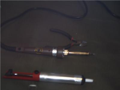
    notice the temp control knob on the iron. off-screen, the iron has a grounding prong. because of that i like to think of it as a soldering station in corded iron form. am i even close to right?

    i probably need an actual stand not a weighted tin can, but i already have the sponge:


    Attached Files
    Last edited by ratdude747; 07-07-2009, 03:28 PM.
    sigpic

    (Insert witty quote here)

    Comment

    • ratdude747
      Black Sheep
      • Nov 2008
      • 17136
      • USA

      #42
      Re: The Recapping FAQ

      i have a different solder sucker now. that other one died when the threads in the tip stripped and shot the tip across the room. i now have a:


      it is all-aluminum, compact, and esd safe. all i hd to do is wd40 the piston and sand down some sharp edges. works great.

      sigpic

      (Insert witty quote here)

      Comment

      • Sigmo
        New Member
        • Apr 2010
        • 4

        #43
        Re: The Recapping FAQ

        I agree with a lot of that. I've been an electronics tech and designer since the mid 1970s, and I have de-soldered and re-soldered thousands if not hundreds of thousands of devices.

        I greatly prefer using a good solder sucker over any other means of removing old solder. You need a good solder sucker and you need to clean it fairly frequently to keep it from barfing out bits of solder. Lubrication is paramount. I prefer Teflon-bearing silicone grease (they used to provide this with RF connectors).

        When the sucker wears out, toss it. They're cheap!

        Very very occasionally, solder braid can be useful, but generally, it's a waste of time and leads to damage.

        The keys to soldering and desoldering are rooted in an understanding of thermodynamics and heat-transfer. If you understand (and have a good gut feel for) Ohm's law, then you understand heat-transfer, too.

        The main thing that damages circuit boards is heat coupled with pressure. Read that again. Heat coupled with pressure.

        Heat alone (as long as you use a temperature controlled iron) rarely damages a circuit board. Pressure alone rarely damages a board. But if you heat a trace AND apply force to it at the same time, that's a recipe for damage. The adhesive that holds the traces in place melts when you get it hot. So if you heat it, do NOT apply force to it at the same time.

        This is where most inexperienced workers get into trouble. They heat up a connection, but not enough to melt the solder completely. So they yank on the component or push on it with the tip of the iron and there you go: The adhesive is melted and now you've pulled or pushed the trace out of place or ripped a plate-through out of the board.

        Normally, the best course is to cut all of the legs off of a device before trying to unsolder them. That way, you can heat and remove them one at a time. You can feel the lead "free up" when the solder is melted, and you can just pull it out with hemostats, needle noses, or tweezers. So for ICs, I just cut off all of the legs (as close to the body of the IC as possible) and then toss the IC body. Then I remove each leg, one at a time very easily, and without damaging the board. Remember: It's the BOARD you're trying to save. The IC is already assumed to be dead or you wouldn't be replacing it!

        But for these caps and some other parts, you cannot cut their legs free of the body before unsoldering. This leads to problems, of course.

        Fortunately, we're dealing with only two leads per cap.

        So you can heat one side and bend the cap away from that heated lead with a small amount of pressure. When the solder melts, the cap will shift. Then you go to the other lead and push the other way on the cap. Again, when the solder melts, the cap will shift.

        Be careful, go slow, wait for the solder to melt and don't use excessive pressure!

        Always apply fresh solder with flux to both connections before starting. You have to "prime" the connections with fresh flux AND more solder. That solder forms a large area bridge between your soldering iron's tip and the board and lead. This is the heat-transfer part of things.

        Imagine a clean soldering iron tip with no solder on it. You want to melt a solder joint where a component lead comes through a plated hole on a board.

        You touch that dry soldering iron tip to that joint, and it touches in a couple of points. Think about that. It touches in a couple of points.

        By definition, a point has zero surface area. How much heat can pass through a point? None!

        You need to increase the surface area between the soldering iron tip and the area you're trying to heat so that heat can pass from the tip to the joint.

        That's where some fresh solder comes into play. It forms a nice "blob" of liquid solder (which is a good conductor of heat) which increases the area through which heat can transfer. In effect, it reduces the "resistance" to the flow of heat just as a larger joint decreases electrical resistance.

        And the fresh flux helps clean off the joint and the soldering iron tip. You MUST have a clean joint and tip for good heat transfer. That burned up crud on the tip is a great insulator. NOT what you want.

        This is another reason to use a temperature controlled soldering iron. When you overheat solder and flux, it burns. It oxidizes and that oxide is a bad conductor of heat and prevents you from tinning the tip. You must have a clean, shiny, tinned tip to get good heat transfer.

        Everything must be clean, shiny, and coated with fresh liquid solder for things to work well.

        The wet sponge is your friend. Wipe and tin the tip over and over.

        And while we're at it, you have to get the joint completely hot. If you're soldering on a large area of foil on a PC board, you will have a challenge. And unfortunately, a lot of these motherboards use very large areas of foil on both sides of the board where the very caps that are most likely to fail are located.

        Use the largest soldering iron tip you can effectively get in there. Large tips hold more heat (think of it as thermal capacitance). They also transfer that heat faster and more effectively because their large cross section has lower thermal resistance. You have to get the heat into the joint!

        If, as with the Soyo boards I've been working on, they have a huge area of foil on both sides of the board for these CPU power supply caps, it's virtually impossible to get both sides of the board hot enough to let you clean the holes out.

        I put one 60 Watt temp controlled iron in a vise and a smaller 40 Watt temp controlled iron in my hand. I just carefully arrange things so that the board can be leaned up against the tip of the iron that's in the vise while I use the hand iron and solder sucker on the other side of the board. I can suck out those holes almost instantly. It's a hassle, but it works great with zero damage to the board.

        If you have someone who can help you, it'll be even faster. Have them hold the board up, standing on one edge. They put one iron's tip on the back side of the hole in question and you use the other iron and the sucker on the other side.

        Again, as counterintuitive as it might sound, put a bit of fresh solder on the hole. You need to have the hole full of fresh solder so you can get the heat to transfer it properly. The sucker can suck it all out in one shot.

        On the subject of suckers:

        A lot of the problems people have with solder suckers stems from their failure to envision and understand what it takes to vacuum solder out of a hole or joint.

        You obviously want to have the greatest suction and flow rate of air possible right at the proper instant.

        To that end, you want to position the tip of the iron and that of the sucker just right. You want to mostly seal off the area, but leave a bit of space for air to rush in so that the sucker's piston can develop some velocity. If you seal things off too well, you actually get a weaker "suck". If you leave too much space, then the air doesn't go where you want it to go, and the solder is not lifted.

        Again, a GOOD solder sucker makes a big difference. It's got to get down on it! Blam! Clean, lubed, a good spring.... Yeah, baby!

        It takes practice, but believe me, it can work fantastically.

        Get in the habit of holding the sucker over a trash can every time you push the plunger down to reset it. That way, the bits of solder don't get everywhere. Lead is toxic. Be careful. Don't eat or smoke while doing this kind of work, and wash your hands when you're done. And be very careful of those nasty wet sponges. They'll be LOADED with lead-oxide in water. Very nasty indeed!

        Wash up when you're done.

        Clean the component side of the board very well and inspect it under magnification before putting the new parts in place. You do NOT want any hair-like threads of solder bridging things under the new parts where you'll never find them. Take the time now because it'll be a pain to try to find the problem later.

        When you solder new parts in place, avoid heating them for too long.

        Use a good, clean, temp controlled iron with a large enough tip to get the job done fast and clean. Remember the heat transfer thoughts. You've got to have melted solder between the tip and the joint to get heat into the joint. So position your rosin-cored solder right there at the intersection of the tip and the joint. All three come together in one small area.

        And imagine pushing the flux-core of the solder into the joint, and even into the plated through hole as you start. That way, a burst of fresh flux floods into the plate-through, around the component lead just as you start. That fresh flux will flow into the joint and down through to the other side of the board under the component and will encourage the solder to "wick" into the annulus between the lead and the hole. Capillary forces will draw the solder in, and it'll make a good joint if there's nice, fresh flux in there.

        When you get good at it, you can make the solder joints quickly and cleanly with very little possibility of any heat damage to the parts or the board.

        I'm sure I'm forgetting something!

        As has been said: Practice up on some junk boards. Play with it all and get comfortable with your equipment, your solder, and the whole mental image of heat transfer. Think about the masses of the things involved (and their heat-storage capacities). Think about the surface areas of things like the foils on the board and imagine how those larger areas pull the heat away from the joint, inhibiting your ability to heat them properly.

        Comment

        • rxtxau4
          New Member
          • Jun 2011
          • 5

          #44
          Re: The Recapping FAQ

          Originally posted by ftaduffy
          I have been in electronics for over 40 years and the best way I found to clean out holes after removing a part is to use compressed air set at about 10 to 15 pounds. USE ONLY A LOW AIR PREASURE!!! THIS MUST BE DONE CAREFULLY!!. I hold the board vertically in a vice by putting some padding one the edge so I do not damage the board. I put a cut down box about a foot in back of the board. Wearing a glove on the hand with the soldering iron I heat the hole while at the same time I hold a blowgun one the other side of the hole. As soon as the solder is melted I press the button on the blowgun and quickly remove the iron. This blows all the solder out. The box collects the solder splatter and the glove protects my hand. CAUTION SHOULD BE USED AND SAFTEY GLASSES SHOULD BE WORN!!.
          A safer way is to get a blower used by watch repairers. There are some that are just a plastic squeeze bulb but the better ones have a plastic body with a piston in them. They are about 50mm in diameter (2 inches) with a thin metal tube coming out the end. Really old ones were all metal & show up from time to time on eBay.

          The military actualy had them in the soldering kits when I was in & used to blow dust out dry off solvent etc.

          A great little item. You would be surprised at the nice jet of air they put out & it is nicely directed.

          Comment

          • s6@riversunhk.com
            New Member
            • Jun 2011
            • 1

            #45
            Re: The Recapping FAQ

            have rubycon capacitor stk , support small qty, 16ZHL ect. have any rfq can contact me !

            Comment

            • power ic
              New Member
              • Sep 2011
              • 2

              #46
              Re: The Recapping FAQ

              i would like to know how to test stk 4142 can someone help me pls

              Comment

              • power ic
                New Member
                • Sep 2011
                • 2

                #47
                Re: The Recapping FAQ

                i would like to test stk 4142 can someone help me pls

                Comment

                • Aikiotto
                  Member
                  • Oct 2011
                  • 30

                  #48
                  Re: The Recapping FAQ

                  Any of you guys used one of these? for component removal

                  http://www.amazon.com/Hakko-Desolder...pr_product_top

                  http://www.amazon.com/Aoyue-474A-Des...0245723&sr=8-1

                  Comment

                  • Evil Lurker
                    Warranty Voider
                    • Feb 2011
                    • 454

                    #49
                    Re: The Recapping FAQ

                    Originally posted by Aikiotto
                    Those are overkill IMO.

                    Most motherboards I encounter have very tight holes and bent leads. If one is not very careful its easy to rip out a via, and/or lift/break a trace, especially with an underpowered iron and RoHS solder. For removing motherboard caps you know are bad, I personally prefer to carefully pull the caps to be replaced off the board by gently rocking them back and forth essentially ripping the leads out of the cap and leaving them on the board, clipping the leads, then desoldering the stubs with at least a 45 watt iron, and finally clearing the holes with desoldering braid and some flux.

                    Single layer boards are a different story. A cheap $12 radio shack desoldering iron with a pump bulb on it is usually more than enough.

                    Comment

                    • Aikiotto
                      Member
                      • Oct 2011
                      • 30

                      #50
                      Re: The Recapping FAQ

                      Originally posted by Evil Lurker
                      Those are overkill IMO.

                      Most motherboards I encounter have very tight holes and bent leads. If one is not very careful its easy to rip out a via, and/or lift/break a trace, especially with an underpowered iron and RoHS solder. For removing motherboard caps you know are bad, I personally prefer to carefully pull the caps to be replaced off the board by gently rocking them back and forth essentially ripping the leads out of the cap and leaving them on the board, clipping the leads, then desoldering the stubs with at least a 45 watt iron, and finally clearing the holes with desoldering braid and some flux.

                      Single layer boards are a different story. A cheap $12 radio shack desoldering iron with a pump bulb on it is usually more than enough.
                      Well yes , heating one pad and rocking the cap on the other is what i do , but my problem is removing the solder inside the hole so the new led can go smoothly in.

                      Perhaps its a matter of practice/experience wich i admith im lacking , so I was looking at some tools and found those two.

                      Comment

                      • Evil Lurker
                        Warranty Voider
                        • Feb 2011
                        • 454

                        #51
                        Re: The Recapping FAQ

                        Originally posted by Aikiotto
                        Well yes , heating one pad and rocking the cap on the other is what i do , but my problem is removing the solder inside the hole so the new led can go smoothly in.

                        Perhaps its a matter of practice/experience wich i admith im lacking , so I was looking at some tools and found those two.
                        Its all about heat, how fast you can apply it, and most importantly practice. Those multilayer boards have copper in between the layers and because of that the PCB acts as a heatsink taking heat away almost as fast as you can transfer it to the joint. The idea is to get the joint completely liquified as fast as possible so you don't overheat and damage the surrounding board. Thats why most people on this board recommend using a 60 watt iron. It also helps if you apply fresh solder to the joint before you attempt to desolder the component as this further speeds your heat transfer.

                        Most people also recommend using a heated stainless steel needle or pick to open up the holes since solder won't stick to stainless. You might try even adding a bit of solder to the hole after the component has been removed then using wick to clear it. Solder has good surface tension, meaning once liquified the solder has a tendency to stay in one puddle like rain drops on a windshield. So, just like if you took a paper towel and touched the edge of a drop of water the desoldering wick would suck up the whole puddle even the solder inside the hole due to capillary action.

                        Gravity also helps since lead is like 12 times heavier than water. I found out by experimenting that if you are a bit adventurous put your pump/wick whatever on the joint while holding the board over your head and let gravity work.

                        Comment

                        • 2xlbu4u
                          New Member
                          • Jan 2012
                          • 1

                          #52
                          Re: The Recapping FAQ

                          Removed.. I've re-posted in the proper location..
                          Last edited by 2xlbu4u; 01-21-2012, 07:46 AM.

                          Comment

                          • pol098
                            Member
                            • Sep 2011
                            • 18
                            • UK

                            #53
                            Re: The Recapping FAQ

                            Long ago, before hearing of the idea of using a stainless steel sharp to clear the hole of solder, I worked out that a pointed wooden toothpick (or cocktail stick) would do the job as solder doesn't stick. It works fine, and I often still use it.

                            Comment

                            • TRWOV
                              New Member
                              • May 2012
                              • 1
                              • Mexico

                              #54
                              Re: The Recapping FAQ

                              I have a question: when selecting replacement caps from the Badcaps store, can I use any capacitor as replacement as long as it has the same capacitance and voltage?

                              For example, let's say that I have a 1200uf 16v KZE... could I use a 1200uf 16v ZLG as replacement?

                              I'm asking because I'm looking at Digikey and there are some concepts that I'm not familiar with, as ripple current, so I don't know if I should lookup the specs and select a matching replacement.

                              As long as the replacement has a <0.1 Ohm ESR is it good to go?

                              Comment

                              • ratdude747
                                Black Sheep
                                • Nov 2008
                                • 17136
                                • USA

                                #55
                                Re: The Recapping FAQ

                                Try to match the ESR with what is being replaced . As a general rule of thumb, if it came from the BCN store, its A-OK for motherboard use.

                                (this question does come up a lot, so it will stay in the FAQ).
                                sigpic

                                (Insert witty quote here)

                                Comment

                                • Gemat
                                  Member
                                  • Nov 2014
                                  • 23
                                  • Ελλάδα

                                  #56
                                  Re: The Recapping FAQ

                                  Hi,

                                  I used to have a hard time clearing the holes on boards after removing the part.

                                  I tried most of the methods described above. On some boards it worked ok, but there were board holes very difficult and time consuming to clean (from multilayered pcbs mostly).

                                  I solved the problem using a rework hot air gun with a 5mm nosle on the part side of the board while heating up the solder side with the iron.

                                  In some cases a milkshake straw can do the job instead of the heat gun...

                                  Comment

                                  • Fast Alpha
                                    Badcaps Veteran
                                    • Feb 2013
                                    • 245
                                    • United Kingdom

                                    #57
                                    Re: The Recapping FAQ

                                    Originally posted by Evil Lurker
                                    Those are overkill IMO.

                                    Most motherboards I encounter have very tight holes and bent leads. If one is not very careful its easy to rip out a via, and/or lift/break a trace, especially with an underpowered iron and RoHS solder. For removing motherboard caps you know are bad, I personally prefer to carefully pull the caps to be replaced off the board by gently rocking them back and forth essentially ripping the leads out of the cap and leaving them on the board, clipping the leads, then desoldering the stubs with at least a 45 watt iron, and finally clearing the holes with desoldering braid and some flux.

                                    Single layer boards are a different story. A cheap $12 radio shack desoldering iron with a pump bulb on it is usually more than enough.
                                    radio shack desoldering iron with a pump bulb on it.
                                    It's funny how they don't sell them in the UK.
                                    http://www.hse.gov.uk/pubns/indg305.pdf

                                    Comment

                                    Related Topics

                                    Collapse

                                    • Tynan Dill
                                      Vizio e601i-A3 - Has Sound and Display, But No Backlight - Bad Power Supply Board or Bad LED Bulbs ?
                                      by Tynan Dill
                                      I was given this TV from my great uncle. He said it just wouldn't turn on one day out of nowhere, replaced the TV, and gave it to me to possibly fix and use for myself.

                                      Upon bringing it home and plugging it up, it showed a standby light.

                                      I powered it on and without a flashlight, the display showed the "V" but the lighting is very dim, but visible.

                                      The screen seems to blackout and stay black, but with a flashlight I can see the display.

                                      With my Playstation 4 connected via HDMI, and running a game I can hear sound.

                                      Assuming...
                                      11-22-2024, 01:46 PM
                                    • m1ch43lzm
                                      HP Pavilion 15-eh Board DAG7HAMB8F0 - CPU throttling to 0.4GHz (PROCHOT_EXT) and black screen
                                      by m1ch43lzm
                                      Hi, this is my personal laptop, which the original board (lets call it Board A) blew up PU8700 (TPS51486), making a hole on the board, i had left the laptop at my desk one day with the battery fully charged and didn't touch it for a week, but when i tried to turn it on it didn't
                                      Thought the battery was dead, so i plugged in the charger then tried to power on, the power LED blinked once, charged LED still orange, unplugged the charger, plugged in again and I noticed the "magic smoke" smell, so i unplugged the charger, removed the back cover and saw the blown IC (the "magic...
                                      05-12-2025, 08:37 PM
                                    • howardc64
                                      A1312 (27” iMac 2009-2011) A1407 (Thunderbolt Display) A1316 (Cinema Display) Display Black Screen Repair
                                      by howardc64
                                      Problem

                                      This is an LG edge LED lit LCD Display. The LEDs are on the bottom edge of the display. There are 2 bars (left and right) Each bar has many LEDs and a 6 pin connector. Each pin drive several LEDs thus is the highest current flow / heat junction. The weak lead free solder gradually fails with thermal expansion/contraction cycling and increases resistance. PSU will compensate up to a point, then when the current is too high, PSU just shut down the backlight causing a dark display. I have even seen one which the connector just fell off as solder points became completely detached....
                                      08-04-2024, 10:36 PM
                                    • Hakuu
                                      LG OLED77G1PUA - No Video / Audio after a TCON Board change and Software Update
                                      by Hakuu
                                      Hi There,

                                      This TV was auto switching off after few seconds with some vertical lines on the screen, so got a new TCON board and replaced it.

                                      After replacing the TCON board it was working fine and i set it up with everything, used for few hours, then had the bright idea to update the software on it. During the update process, TV switched off and now no audio or video. No relay switch sound.

                                      More Details

                                      TV Model - LG OLED77G1PUA

                                      Got the same exact TCON board from TVPartsToday and replaced it. But didnt transfer the EPPROM data (didnt...
                                      07-12-2023, 02:37 PM
                                    • jb_Bak
                                      Sony xbr-65x900c main board issues?
                                      by jb_Bak
                                      Hey guys great forum glad to have found it. I bought a Sony XBR 65X900C cheaply because it didn't work. No signs of life at all not even a light/led. All I hear is a brief high voltage sound when I throw the power to it.

                                      Didn't see any obvious signs of damage so right away started checking voltages. This is what I see:
                                      Power Board Connector that goes to Main board
                                      CN6401
                                      Pin 01 NC
                                      Pin 02 NC
                                      Pin 03 "BL_ON": 0V
                                      Pin 04 "N/C"
                                      Pin 05 "STBY 3.3V": 3.5V
                                      Pin 06 "GND": N/C
                                      Pin 07 "AC_OFF"...
                                      09-27-2021, 04:52 PM
                                    • Loading...
                                    • No more items.
                                    Working...