![]() |
|
|
Thread Tools | Display Modes |
![]() |
#1 |
New Member
Join Date: Aug 2010
City & State: Dallas, TX
Posts: 12
|
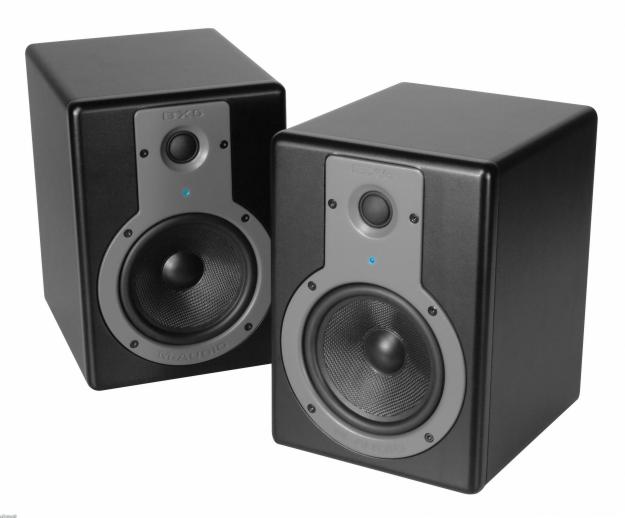
![]() M-Audio BX5-a Studio Powered Monitors Bad Capacitors.
Looks like M-Audio is another victim on this issue. If you check the official forum the only response is from the consumers, but there is no word from M-Audio. http://forums.m-audio.com/showthread...a-died-on-me-( I've fixed my pair and replaced the faulty capacitors. (Unknown brand), 25v 6800μF (105°C). 
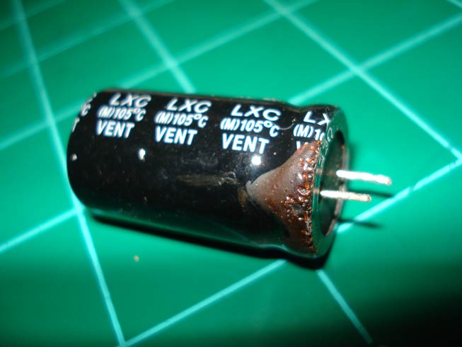
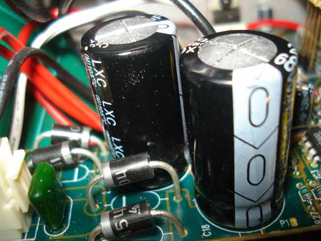
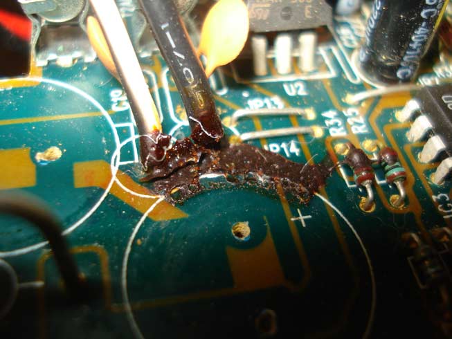
Replaced with Cornell-Dubilier Capacitors, and now both monitors are working like new. ![]() ![]() ![]() ![]() ![]() |
![]() |
![]() |
![]() |
#2 |
Super Moderator
Join Date: Jul 2005
City & State: ----
My Country: Sweden
Line Voltage: 230v 50Hz
I'm a: Knowledge Seeker
Posts: 4,672
|
![]() What you see on the bottom is just glue
The tops are bulged tho, good catch I'm glad to hear it's working fine now! Also, Welcome to Badcaps!
__________________
"The one who says it cannot be done should never interrupt the one who is doing it." Last edited by Per Hansson; 08-12-2010 at 10:42 AM.. |
![]() |
![]() |
![]() |
#3 |
New Member
Join Date: Aug 2010
City & State: Dallas, TX
Posts: 12
|
![]() Looks like that's it.
I am not dealing with leaked capacitors every day, so I wanted to see an UFO and I did. The fact is that all those M-Audio monitors are going down one by one for the same reason, so I thought the cap was already leaking. It was bad enough that the monitor wasn't working anymore. Thank you for the welcome, this is a great forum. |
![]() |
![]() |
![]() |
#4 |
Badcaps Veteran
Join Date: Jul 2007
City & State: East Coast, USA
Line Voltage: 220-221
I'm a: Professional Tech
Posts: 4,145
|
![]() Welcome.
The glue becomes brown(er) as it ages then it becomes conductive. It should be completely removed. Replace with your favorite brand silicone glue/caulk. I'm assuming these monitors use a linear not switch mode power supply(SMPS). Linear would have a step down transformer hooked to the mains plug and the secondary winding feeding the board(s). CDE caps are fine for this and other linear PSU applications; be aware that they do not have a high enough quality line for use in SMPS other than for mains filtering (250-400v caps). I would also recommend that you replace any caps of this unknown brand that have the vent marking on the top. Cheers! Toast Last edited by Toasty; 08-12-2010 at 03:00 PM.. Reason: rewording |
![]() |
![]() |
![]() |
#5 | |
New Member
Join Date: Aug 2010
City & State: Dallas, TX
Posts: 12
|
![]() Quote:
This is already done. The replacement are Cornell Dubilier Electronics caps. I assume that there is nothing wrong with Cornell since I couldn't find nothing against them. ... and yes, the board was cleaned. ![]() |
|
![]() |
![]() |
![]() |
#6 |
Badcaps Veteran
Join Date: Jul 2007
City & State: East Coast, USA
Line Voltage: 220-221
I'm a: Professional Tech
Posts: 4,145
|
![]() CDE = Cornell Dubilier Electronics
Let me say this another way- I was pointing out that CDE caps are fine here, but not in the other units you are currently posting about ~except~ for the mains caps. Toast ![]() |
![]() |
![]() |
![]() |
#7 | |
New Member
Join Date: Aug 2010
City & State: Dallas, TX
Posts: 12
|
![]() Quote:
I think all the problems on my audio equipment is related to the power supply only, so I am not going to do anything more to the board until I replace the power supply caps. Cheers! |
|
![]() |
![]() |
![]() |
#8 |
New Member
Join Date: Jan 2021
City & State: Pirkanmaa
My Country: Finland
I'm a: Knowledge Seeker
Posts: 5
|
![]() Hi guys,
this is my first post here in the forum, so I thought I will recycle this old thread.. I am Oliver from Germany, currently living in Finland... I soldered quite a bit in the past, mainly built tube amps, guitar effects, repaired my pinball machine with some guidance and this kind of stuff... However, I am more of an IT guy, but not a studied electronic engineer, so I have some basic understanding of circuits but not too much.. Always willing to learn though, fascinating topic ![]() ![]() I have similar problems with an M-Audio BX5a speaker.. First, the bass speaker started making farting sounds, getting worse over some months, but I thought I just broke it by playing bass guitar over them quite loud.. After some weeks, it stopped working completely and blew the F2 fuse.. However I have replaced the two big 6800μF filter capacitors, since then, but it still didn't work.. Keeps blowing F2 fuse.. Next I replaced the negative voltage regulator since I had only -7V at the output of it instead of -12V I guess its supposed to be... Running the speaker with a light bulb in line, it doesn't blow the fuse and I can measure a bit at least.. I checked the working speaker, and I have identical voltages at the inputs from transformer, the 4 diodes, fuses etc.. However on the broken speaker I have a constant positive (I think) current on both treble and bass speakers (around +3 to +5V if I remember correctly?) which presses them out after switching on (and blowing F2 if run without the light bulb). Sorry, I measured that stuff 2 weeks ago, so don't recall exactly, but I can measure it again if needed.. Unfortunately at some point I ran them for a minute without the cooling block resulting in some smoke, around the amp transistors, not sure exactly though where that came from, so I hope I didn't break even more things now.. To sum it up, I am a bit desperate at the moment, I didn't find circuit schematics anywhere for these speakers, and I don't want to start changing random caps now, since the board seems extremely fragile also, when de-soldering I have to be very careful to not destroy the soldering eyes... So if you have any suggestions what I could start swapping next, would be extremely appreciated.. Thanks in advance and greetings from Finland! Oliver |
![]() |
![]() |
![]() |
#9 |
Badcaps Veteran
Join Date: Sep 2006
City & State: Valkeakoski
My Country: Finland
Line Voltage: 230VAC 50Hz
I'm a: Professional Tech
Posts: 1,245
|
![]() Well, some internal photos might help. Since these weren't exactly "high-end" to begin with, it's safe to assume they stuck with pretty simple / conventional circuitry.
But if you're getting DC on the speaker outputs, that points to possibly dead amplifier chips (or some DC-trouble ahead of them, in case there's no DC-blocking capacitor at the amplifier inputs, but that's doubtful).
__________________
Khron's Cave - Electronics - Audio - Teardowns - Mods - Repairs - Projects - Music - Rants - Shenanigans |
![]() |
![]() |
![]() |
#10 |
New Member
Join Date: Jan 2021
City & State: Pirkanmaa
My Country: Finland
I'm a: Knowledge Seeker
Posts: 5
|
![]() Hi,
thanks a lot Khron for your post! I will put some photos... On one of them you can see the bad filter cap(s) clearly, but as said changing them didn't help much.. If more photos needed just let me know.. The ripped off soldering eyes don't look so nice but connectivity is still there.. I am wondering still about the low voltage on the negative regulator.. Is there anything I could check around that one, or does that have possible other reasons, like the amp chips? Thanks in advance! Oliver |
![]() |
![]() |
![]() |
#11 |
Badcaps Veteran
Join Date: Sep 2006
City & State: Valkeakoski
My Country: Finland
Line Voltage: 230VAC 50Hz
I'm a: Professional Tech
Posts: 1,245
|
![]() Are both fuses still intact? And/or are the "main" +/- DC voltages across the big caps, what they should be? With 25V caps, probably +/-20V DC or so.
There's a chance that, since that one electrolytic blew, it could've taken out one or two of the four rectifier diodes, so you'll probably want to check those too (check all four, just to be sure). |
![]() |
![]() |
![]() |
#12 |
Super Moderator
Join Date: Jul 2005
City & State: ----
My Country: Sweden
Line Voltage: 230v 50Hz
I'm a: Knowledge Seeker
Posts: 4,672
|
![]() Check what Khron suggested, and also resolder the circled areas in my attached photo:
The connector is loose and you can easily fix your capacitors better by using a knife to scrape away some soldermask to expose some copper underneath. |
![]() |
![]() |
![]() |
#13 |
New Member
Join Date: Jan 2021
City & State: Pirkanmaa
My Country: Finland
I'm a: Knowledge Seeker
Posts: 5
|
![]() Thanks guys!
I will do what you both suggested and then report back when I have some more info / re-soldered those! ![]() |
![]() |
![]() |
![]() |
#14 |
New Member
Join Date: Jan 2021
City & State: Pirkanmaa
My Country: Finland
I'm a: Knowledge Seeker
Posts: 5
|
![]() Hi guys,
damn now I wrote rather extensively and then I failed when uploading the pics so text disappeared, I will write again, a bit shorter.. I resoldered the spots today, good catch, the one for the LED in the corner! Seems now the caps are properly connected at least, still problem remains though... So I measured the diodes with and without fuses, it looks like this: WITHOUT FUSES: Transformer I think was around 23.7~ twice. PLUS / MINUS D1 24VAC/50Hz / +24DC / 0 AC D2 24VAC/50Hz / +24DC / 0 AC D3 -24VDC /0VAC / 24AC 50Hz D4 -25VDC /0VAC / 24AC 50Hz DC voltages stay on from capacitors after switching off. C1 - -24.4DC + 0VDC C2 + +24.4DC - 0VDC So now when I put in the fuses I have the following: It presses out the bass driver quite a bit, seems to suck in treble driver, and instantly blows F1. So to measure I put a 60W light bulb in line of the 220V and which glows quite strong, so there must be some kind of serious short somewhere I guess.. With it, it doesn't blow F1 at least and I can measure.. I think without the bulb the 8V voltages are higher, probably around 12, but I checked only very shortly since I don't have so many fuses ![]() WITH FUSES AND LIGHT BULB: + - D1 8VAC / +8VDC (plus some under 1V 100Hz stuff there on all 4 diodes) D2 8VAC / +8VDC " D3 -7.2VDC / 8VAC D4 -7.2VDC / 8VAC C1 - -7.2DC C2 + +7.6DC The AC on the diodes looks different also with fuses, it was nice 50HZ sinus waves without the fuses, but with, they get more like squares, see attached photo. Also the DC doesn't look too clean anymore ![]() So could we say the power supply part is alright and the problem is later, or cannot say that either yet? ![]() Thanks in advance, guys, I hope this make sense... Greetings, Oliver |
![]() |
![]() |
![]() |
#15 |
Badcaps Veteran
Join Date: Sep 2006
City & State: Valkeakoski
My Country: Finland
Line Voltage: 230VAC 50Hz
I'm a: Professional Tech
Posts: 1,245
|
![]() Could both chip-amps be blown?
![]() |
![]() |
![]() |
![]() |
#16 |
New Member
Join Date: Jan 2021
City & State: Pirkanmaa
My Country: Finland
I'm a: Knowledge Seeker
Posts: 5
|
![]() Thanks Khron and Per Hansson for your help so far, much appreciated!
Yeah who knows, I wouldn't exclude that I broke those amp chips somewhere on the way ![]() I have ordered now a couple of TDA2052 from China, so that will take some weeks I am afraid, but once they are here I will solder them in and report back if that helped... Cheers, Oliver |
![]() |
![]() |
![]() |
Thread Tools | |
Display Modes | |
|
|