Announcement

Collapse
No announcement yet.

Crack & Stink Gigabyte GA7N400 Pro 2

Collapse
X
 
  • Filter
  • Time
  • Show
Clear All
new posts

    #21
    Re: Crack & Stink Gigabyte GA7N400 Pro 2

    update:
    re-tested the psu and it started to smoke
    so, looks like the crack sound, and the odor, was the caps blowing their vents?
    didn't know that a psu could destroy a mobo, and assumed that they would all have over-current protection as a basic feature.
    this is the first time that i've ever seen a psu die (and unfortunately, also "take-out" a mobo with it).

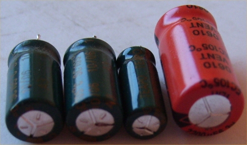
    here is the pic of the caps:
    two are domed, and the other two (teapo) have opened up
    Attached Files
    Last edited by socketa; 07-03-2014, 05:11 PM.

    Comment


      #22
      Re: Crack & Stink Gigabyte GA7N400 Pro 2

      It's not uncommon for cheap PSUs to turn nasty and kill boards, actually. The cheap ones also have a lack of decent protection for anything they are powering or themselves, too.

      The crack was probably the southbridge going up in smoke, but could have been one of the capacitors. Possibly your PSU had a faulty 5vSB regulator circuit sending too high a voltage into the motherboard. Or there is some regulation problem on the main rails, maybe even a totally shorted rectifier allowing AC out into the motherboard.

      What brand and model is the PSU?
      "Tantalum for the brave, Solid Aluminium for the wise, Wet Electrolytic for the adventurous"
      -David VanHorn

      Comment


        #23
        Re: Crack & Stink Gigabyte GA7N400 Pro 2

        And that would be why really cheap generic power supplies should never ever under any circumstances be used, purchased or sold. (at least not without being recapped and modified)
        Last edited by c_hegge; 07-03-2014, 06:37 PM.
        I love putting bad caps and flat batteries in fire and watching them explode!!

        No wonder it doesn't work! You installed the jumper wires backwards

        Main PC: Core i7 3770K 3.5GHz, Gigabyte GA-Z77M-D3H-MVP, 8GB Kingston HyperX DDR3 1600, 240GB Intel 335 Series SSD, 750GB WD HDD, Sony Optiarc DVD RW, Palit nVidia GTX660 Ti, CoolerMaster N200 Case, Delta DPS-600MB 600W PSU, Hauppauge TV Tuner, Windows 7 Home Premium

        Office PC: HP ProLiant ML150 G3, 2x Xeon E5335 2GHz, 4GB DDR2 RAM, 120GB Intel 530 SSD, 2x 250GB HDD, 2x 450GB 15K SAS HDD in RAID 1, 1x 2TB HDD, nVidia 8400GS, Delta DPS-650BB 650W PSU, Windows 7 Pro

        Comment


          #24
          Re: Crack & Stink Gigabyte GA7N400 Pro 2

          ISO-450PP 4S

          Yes, i now know that it is a hunk of junk

          Prior to this, had seen quite a few of them, and thought that they must be OK, otherwise the manufacturer would get a bad reputation and no one would by their products, and their business would collapse.

          But since i had no idea, i guess that neither would many others, and it would be too much of a hassle for some to find out what happened, and they would just throw the PC in the rubbish bin, and then buy another time bomb.
          Last edited by socketa; 07-03-2014, 07:11 PM.

          Comment


            #25
            Re: Crack & Stink Gigabyte GA7N400 Pro 2

            There are many PSU manufacturers with bad reputations - on this forum.

            The problem is most people don't know how crap some of them can be, it helps that often they upgrade them before they fail anyway.

            Even if enough of them died to make everyone know how bad they were, the OEM would just relabel it next month - like the way the brand names on the stickers seem to change every couple of years anyway...
            "Tantalum for the brave, Solid Aluminium for the wise, Wet Electrolytic for the adventurous"
            -David VanHorn

            Comment


              #26
              Re: Crack & Stink Gigabyte GA7N400 Pro 2

              Originally posted by socketa View Post
              Appreciate you guys (which, of course, may include non-male guys) taking a look at this.
              That fet is not cracked,
              i think you might be looking at the shadow.
              Also note that the photo didn't show the short middle drain pin (but it's there).

              However, then had a look at the south-bridge
              Rubbed finger across it and felt a very fine ridge on it's surface.
              At first, thought it was the printing on the surface, but upon closer inspection there is, what appears to be, the tiniest little crack in it.

              Previously didn't get spend too much time over it, thinking that the south-bridge controlled the peripheral ports - not the on/off switch that starts up the PSU

              So is that a good sign that it's knackered?
              Can i test it with a meter?
              Can a such noticeable odor, come through such a miniscule crack?

              Also tested the big mosfets, 3 of them had shorts, from drain to earth and from source to drain.
              All 6 of them had shorts from source to earth
              So are these last 3 OK because they don't have shorts from drain to sink and perhaps have their sources connected directly to earth?

              For the sake of completeness, here is the visual of the suspected crack, that might have resulted from the audible crack - it's between the V and the I
              I once had a Epox 8rda+pro NF2 get hit by a lightning strike from about 30 feet away, Ethernet cable plugged in, no power cable connected. The board still work well but the onboard nic chip was fried brown colered in the center and could not hold a finger on it for more than 2 seconds.

              Comment


                #27
                Re: Crack & Stink Gigabyte GA7N400 Pro 2

                Originally posted by c_hegge View Post
                And that would be why really cheap generic power supplies should never ever under any circumstances be used, purchased or sold. (at least not without being recapped and modified)
                Unfortunately they work just fine long enough for most people, so they don't know or care.

                Comment


                  #28
                  Re: Crack & Stink Gigabyte GA7N400 Pro 2

                  That ISO-450PP 4S is a CWT (Channell Well Technology) PSU.

                  The ISO series is their budget line and varies in quality anywhere between very decent and plain-straight crap. Usually the crappy ones are bought and re-branded by "fly-by" companies, such as Cyberlink and Turbolink (common gutless wonder PSUs that come with cases), and I think OKIA as well.

                  The ISO line is based on a very old and inefficient, but also very stable design - the half-bridge. However, the real kicker is that the ISO line use a 2-transistor 5VSB circuit that has a "critical" cap. If the critical cap fails, 5VSB can overshoot very high - sometimes as much as 12V to 13V. USB devices and older motherboards often can't handle this overvoltage, so they fail. The ISO line is known to use crap caps such as Fuhjyyu, so that "if the critical cap fails" always becomes a "when the critical cap fails" - i.e. inevitable disaster unless the PSU is completely recapped pre-emtively.

                  That said, your PSU may still be salvegable if you are up for "fun" project. If it's decently made (crap-caps aside), a recap with high-quality caps can make it work like new again and actually last for many years.

                  Comment


                    #29
                    Re: Crack & Stink Gigabyte GA7N400 Pro 2

                    just found the culprit that made the stink (and possibly the crack)
                    am guessing it was caused by one or two bad caps (photo in previous post) stressing the resistor out?
                    it was well hidden under a choke, and behind a cap

                    now am trying to locate a circuit diagram for an ISO-450PP 4S to work out: if one of these 4 caps failed, which one would lead to the overheating of the resistor.

                    in hindsight, after being quite ignorant when it comes to this stuff, have learned a few lessens
                    don't assume a psu is good just because the psu case looks clean and tidy
                    don't assume that the smell is coming from the mobo
                    and as a consequence of this ignorance, and help from here, now have a few clues as to what's what.


                    Attached Files
                    Last edited by socketa; 07-10-2014, 11:40 PM.

                    Comment


                      #30
                      Re: Crack & Stink Gigabyte GA7N400 Pro 2

                      Unfortunately, PC PSUs practically have no schematics available. They are not considered worth repair since they are all interchangeable anyway. There are basic reference designs and of course controller datasheets etc to give some idea but that's about it.

                      If you know the general layout of a SMPS you can trace what the resistor connects to and find out (probably) what it's for, otherwise, it would be tricky if you don't.

                      Post photos of the whole PSU to show resistor location relative to everything else, and also top down, and a bottom side photo of the tracks including which pads are the resistors and we might be able to help figure it out.

                      Resistors usually burn when something they supply power to is shorted, or they see an overvoltage condition.
                      "Tantalum for the brave, Solid Aluminium for the wise, Wet Electrolytic for the adventurous"
                      -David VanHorn

                      Comment


                        #31
                        Re: Crack & Stink Gigabyte GA7N400 Pro 2

                        thanks
                        spent a couple of hours searching, to no avail

                        so a dud cap would be very unlikely to have caused this?

                        there is a short to ground (6.2ohm) on the mobo 3v rail
                        but perhaps that could have being caused by over-voltage from the psu.

                        not going to fix this psu, but would like to have some rough idea as to what caused this

                        have probably snapped the legs of a couple of components as i was moving them

                        ... so the pics are probably not necessary, but have included them anyway
                        Attached Files
                        Last edited by socketa; 07-11-2014, 05:29 PM.

                        Comment


                          #32
                          Re: Crack & Stink Gigabyte GA7N400 Pro 2

                          If the output capacitors died in the PSU it's possible the PSU became unstable to the point that components would be damaged, and also resulted in the death of the motherboard.

                          I don't know where the resistor goes from your photo, unfortunately, but if you're not going to attempt repair I guess it doesn't matter.
                          "Tantalum for the brave, Solid Aluminium for the wise, Wet Electrolytic for the adventurous"
                          -David VanHorn

                          Comment


                            #33
                            Re: Crack & Stink Gigabyte GA7N400 Pro 2

                            Originally posted by socketa View Post
                            thanks

                            there is a short to ground (6.2ohm) on the mobo 3v rail
                            No, there's minimum load resistors on 3.3v and 5v to keep the output within regulation. Think there's even minimum load resistors on 12v and -12v but not sure.

                            3.3v 6.2 ohm .. v = i x r => i = 3.3/6.2 = 0.53A P = IxIxR = 0.53 x 0.53 x 6.2 = 1.7w

                            That looks like a 3w resistor to me, so the math works out:

                            Attached Files

                            Comment


                              #34
                              Re: Crack & Stink Gigabyte GA7N400 Pro 2

                              Originally posted by socketa View Post
                              just found the culprit that made the stink (and possibly the crack)
                              am guessing it was caused by one or two bad caps (photo in previous post) stressing the resistor out?
                              I'm guessing this is the same PSU in this thread:
                              https://www.badcaps.net/forum/showth...392#post463392

                              I traced the circuit. That resistor supplies the PWM controller with power (that 8 pin DIP IC). Looks like indeed scenario #2 (from post #13 I made in that thread above) was what happened here - i.e. caps on the output of the 5VSB went bad, so the 5VSB regulation went bad too. This made the secondary-side auxiliary supply for the PWM controller go over-voltage and probably killed the PWM IC ar/or made it do weird things.

                              Third time I see this now on a 2-transistor 5VSB design. I just recalled that I had another PSU - a Morex MXA-235PTF1 with the same problem (though, it's resistor didn't get to cook quite yet and so PWM controller seems to have survived). I recapped the 5VSB output on it with good caps, and it's rock-stable at 5.02V now.

                              Originally posted by socketa View Post
                              there is a short to ground (6.2ohm) on the mobo 3v rail
                              Most likely you are reading a minimum load resistor, as mariushm suggested. Not uncommon to see 2W or 3W resistors between 4.7 Ohms and 47 Ohms on the 3.3V rail. Your 5V rail seems to have one too. Probably 27 Ohms or 47 Ohms (I find these most common).
                              Last edited by momaka; 07-12-2014, 12:12 PM.

                              Comment


                                #35
                                Re: Crack & Stink Gigabyte GA7N400 Pro 2

                                Just in case there is any misunderstanding,
                                When i said that "there is a short to ground (6.2ohm) on the mobo 3v rail",
                                i was not referring to the 3.3v rail on the psu - but rather, the motherboard

                                Hence, was thinking that this low resistance to ground (on the motherboard 3.3v rail), perhaps via a burned-out southbridge - may have cooked the resistor,
                                as agent24 suggested

                                But now can see that if a psu has a minimum load resistor on a rail (to ensure a minimum current), then so might a motherboard,
                                so the 6.2ohm reading might be due to a minimum load resistor on the mobo - rather than a short.

                                Anyway thank you, guys, for highlighting the caps with rails colors and for the explanation/interest.

                                Am guessing that since the psu diagrams, that i'm looking at, don't have that 8-pin DIP IC, that transistors would be doing that job in those diagrams

                                So that yellow area contains the output caps for the 5vsb
                                Noticing how it wiggles to the left a bit, does that imply that it would also include the cap that i removed?
                                If so, then it is that little one in post #21 - (the one that has bulged and opened-up the most)
                                Last edited by socketa; 07-13-2014, 03:15 AM.

                                Comment


                                  #36
                                  Re: Crack & Stink Gigabyte GA7N400 Pro 2

                                  Originally posted by socketa View Post
                                  But now can see that if a psu has a minimum load resistor on a rail (to ensure a minimum current), then so might a motherboard,
                                  so the 6.2ohm reading might be due to a minimum load resistor on the mobo - rather than a short.
                                  The PSU has minimum load resistor(s) to keep it working correctly and stable, the motherboard doesn't need one because it's not a PSU, it is a load.
                                  "Tantalum for the brave, Solid Aluminium for the wise, Wet Electrolytic for the adventurous"
                                  -David VanHorn

                                  Comment


                                    #37
                                    Re: Crack & Stink Gigabyte GA7N400 Pro 2

                                    Originally posted by socketa View Post
                                    Hence, was thinking that this low resistance to ground (on the motherboard 3.3v rail), perhaps via a burned-out southbridge - may have cooked the resistor,
                                    as agent24 suggested

                                    But now can see that if a psu has a minimum load resistor on a rail (to ensure a minimum current), then so might a motherboard,
                                    so the 6.2ohm reading might be due to a minimum load resistor on the mobo - rather than a short.
                                    No, motherboards don't need load resistors. In order to adjust the number of pulses going through the transformers, the power supply needs to monitor the output voltage on a rail and adjust accordingly. However, the power supply is tuned to keep the voltage through a wide range of current output, let's say from 1 to 30A.
                                    It's just not able to monitor the output voltage properly at extremes (0A for example) so it adds that resistor to use 0.3-0.5A all the time.

                                    The motherboard doesn't produce output, it just takes whatever it gets so there's no load resistors. You probably have a short somewhere. In theory, you could determine the short location with a good multimeter - put it in resistance mode, put black probe on ground somewhere and with the red probe, you can follow the pcb trace for 3.3v. As you get close to the short, the resistance should decrease (but by milliohms, so again you need a good multimeter)

                                    So that yellow area contains the output caps for the 5vsb
                                    Noticing how it wiggles to the left a bit, does that imply that it would also include the cap that i removed?
                                    If so, then it is that little one in post #21 - (the one that has bulged and opened-up the most)
                                    No. Colors are (sort of) standardized. Orange is 3.3v, red is 5v, yellow is 12v.
                                    There's only one wire for 5v standby which is usually purple, white is -12v and blue is -5v
                                    But since -5v is no longer required and they may have used blue for 5v standby. Just check the atx connector, see the wire color... i posted the atx connector pinout in another thread of yours but if you can't find it just google "atx psu pinout" or something like that.

                                    Comment


                                      #38
                                      Re: Crack & Stink Gigabyte GA7N400 Pro 2

                                      Yes, i get the pin-out
                                      Had a tiring day and wasn't thinking straight and said 5v, while meaning 12v
                                      (had being so focused on a 5vsb diagram, that the number 5 was stuck in my mind)

                                      So, could that 6.2ohm low resistance on the 3.3V rail (on the actual motherboard), a possible trigger that could have initiated the frying of that resistor on the PSU?

                                      i get the feeling that that was probably not the case.
                                      And that this low resistance fault? is possibly due to a south-bridge that was damaged by the PSU
                                      (seem to recall reading that the south-bridge can sometimes be powered by the 3.3v rail)

                                      Now regarding the PSU,
                                      i now see, after following the traces, that the small green cap is on the 12v rail,
                                      the 2 middle sized green caps are on 5vsb rail,
                                      and the big orange one is for 3.3v rail,
                                      (thumbnail picture provided below)

                                      Additionally,
                                      Testing from either side of that burned-out resistor:
                                      No hard shorts to any rails or ground
                                      One side goes to the Vcc pin of the 16-pin PWM control pin, and the other side goes to a diode (which shows no continuity, but gives good diode test - so that looks like a zenner diode)

                                      Is the most likely initial cause of this incident (the dead mobo+PSU) due to the worn-out caps degrading the performance the performance of 3.3v, and the 5vsb rails?,
                                      (where excessive voltage on either of these rails, would likely result in motherboard damage)

                                      Further testing, in continuity mode, gives a continuous beep, and 15.3 ohms, across the position where that that big red cap was on the 3.3v rail.

                                      cheers
                                      Attached Files
                                      Last edited by socketa; 07-13-2014, 08:03 PM.

                                      Comment


                                        #39
                                        Re: Crack & Stink Gigabyte GA7N400 Pro 2

                                        Again.

                                        There's no 5v SB rail... 5v SB (stand by) is just ONE WIRE. The red wires are 5v which is produced by a different section of the power supply.
                                        So you have 5v standby , normal 5v , 3.3v , 12v , -12v and possibly -5v. SEPARATE 5v SB and SEPARATE 5v.

                                        You have two capacitors on each 3.3v/5v/12v rail because you have on each rail a PI filter ... capacitor -> inductor -> capacitor. This helps smooth out the ripple, makes the voltage more stable. Those coils of wire on a black tube are the inductors.

                                        The big round things with wire are chokes/inductors but they're used in a different way.

                                        Those inductors will be HOT during operation, especially at high currents. The load resistors on each rail will also be HOT. The fan moves the air around so there won't be during normal operation spots of heat but still that area will get warm.

                                        Capacitors heat up due to electricity going through them, they heat up due to leads and traces bringing heat from the inductors and the load resistors and so on. In time, this heat will damage very slowly the capacitors, the capacitors will change their electric characteristics which may just mess up the circuit and cause some part of the power supply to work erratically or "stress" itself more than normal, which in turn can damage other parts.. you basically have a cascade, a chain effect...


                                        gives a continuous beep, and 15.3 ohms, across the position where that that big red cap was on the 3.3v rail.


                                        Again, as long as you have those load resistors on the PCB, they're going to screw up your measurements.

                                        Your multimeter shows continuity as long as the resistance is below a threshold, let's say 20 ohm (it varies from meter to meter).

                                        It then says 15 ohm, which could be the load resistor, it could be something else. The load resistor is between + 3.3v and ground and the capacitor leads are on +3.3v and ground, so you're measuring across that load resistor.

                                        15.3 ohms is about right for a 15 ohm +/-5% resistor and about right for a load resistor . V = I x R => 3.3v = I x 15 => I = 0.22A so the resistor makes sure there's always at least 0.22A drawn from the 3.3v rail.

                                        ps. And I don't know what the hell you mean with the first picture because - as I already complained in a previous post - you cropped the picture (again) in such a stupid way that I can't be bothered to try to determine where it's located in the power supply.
                                        Last edited by mariushm; 07-13-2014, 08:22 PM.

                                        Comment


                                          #40
                                          Re: Crack & Stink Gigabyte GA7N400 Pro 2

                                          The pic was only to make sure that the component circled was a zenner diode - that's all

                                          Anyway, i didn't know that those chokes got hot.
                                          So, perhaps that also contributed to the resistor burning up, since it was directly underneath it, and also surrounded by 3 caps.

                                          Again, as long as you have those load resistors on the PCB
                                          Which PCB are you referring to?
                                          i was clearly referring to the measurement that i got from the motherboard.
                                          But if by "load resistors" you mean "minimum load resistors" it seems that you are referring to the PSU.
                                          Furthermore, i understood what agent24 said.
                                          the motherboard doesn't need one because it's not a PSU, it is a load.
                                          before submitting my last post.

                                          If you re-read my posts on this page, i tried to make it very clear that i was referring to the motherboard when i took this 6.2ohm measurement.

                                          This line of thought was initially prompted when agent24 said:
                                          Resistors usually burn when something they supply power to is shorted, or they see an overvoltage condition
                                          So was thinking that this "short" could be on the motherboard, which, in-turn , could upset the PSU.

                                          OK, so was using the term "rail" incorrectly,
                                          and should be using "output" instead.
                                          Lesson learned
                                          Last edited by socketa; 07-14-2014, 02:47 AM.

                                          Comment

                                          Working...
                                          X