Re: Fish Tank LED Power Supply Gets Hot then shuts down
I have at least FIVE of those exact same LCD displays that I bought in a cheap group from Amazon just to have some, I'll fire one up and see what kind of current it draws ... though it will be a unit that is close to 20 years older in design than this one, but I can't imagine they have changed all that much. They look identical except for the connection methods.
I think this is where everyone responding to this post has gotten confused. I tried to spell it out as detailed as I could, but admittedly I've posted a lot of information and even had to correct some mistakes so lets cover that right here and now...
The power lines that come in from the PSUs are of course of two types: +5v and +12v
The 5 volt lines ONLY DRIVE LEDs ... the 5 volt lines have NOTHING TO DO with the main controller board OR that wire that melted.
The wire that melted is a tap on the +12 AND GROUND from one of the PSUs, and that wire directly feeds the 7805 that powers the main controller board.
So whatever melted that wire, was from a high current draw on the main controller board. Now that could have been a fan that went bad (as one of them wont power on at all, and it is not shorted either, but I did see that the ground cable on that fan was disconnected at the fan itself and there was some obvious corrosion around those connection points. The wire was soldered onto a PCB at the center of the fan, but it just somehow broke off at the solder point. When I barely tugged on the red wire on that same fan it also came off of its solder point ... since this light assembly sits above a fish tank 24 / 7, moisture is going to be an issue and if its a salt water tank, then that will be even a worse problem.
BUT even though that fan went bad, none of the fan wires were melted or showed any kind of problem at all.
The only damage that we see, is the melted wire, which carries +12 AND GROUND from the PSU to the 7805 on the main controller board. Then on the main controller board, we see burn marks on the PCB directly around the 7805 and also at various points along the GROUND TRACE on the under side of the PCB ...
I want to throw out this thought concerning the +5 and the amperage I saw it taking when I connected the unit to a PSU ...
At that time when I took that reading, I had not taken apart the main unit. So I have no idea which of the two PSU lines inside the unit I was taking that reading from. As one PSU line is split off inside the housing and those lines are connected to TWO LED panels. And those PSU wires go no where else. The other PSU wire connects to the third LED panel but its +12 is tapped to power the main controller board.
Now since +5 ONLY powers LEDs and those LEDs are in parallel, I am suggesting that the amperage we saw might be just fine if we assume that those LEDs can suck a lot of amps... powering 10 sets of two LEDs in parallel (on one PSU and then only 5 sets of parallel LEDs on the other PSU) could add up to 5.5 amps if I was connected to the LED panels that drive 10 sets of two in parallel ... if one set of parallel LEDs consumes only 400ma we're close to 5 amps already. I have LEDs that I can drive safely at 250ma PER LED ... two in parallel is half an amp, then ten of those is 5 amps.
I don't think the +5 amperage issue is of any concern ... the real problem is what happened along that +12 that feeds power to the main controller board - and the evidence for that statement exists in the fact that those wires were melted and there are burn marks on the board that those wires feed. There is no other damage anywhere else in the entire unit. No damage at the LED panels or their driver boards and I did check all of the LED strips and nothing is shorted ... I checked all 15 rows of LEDs and confirmed that they are all working properly.
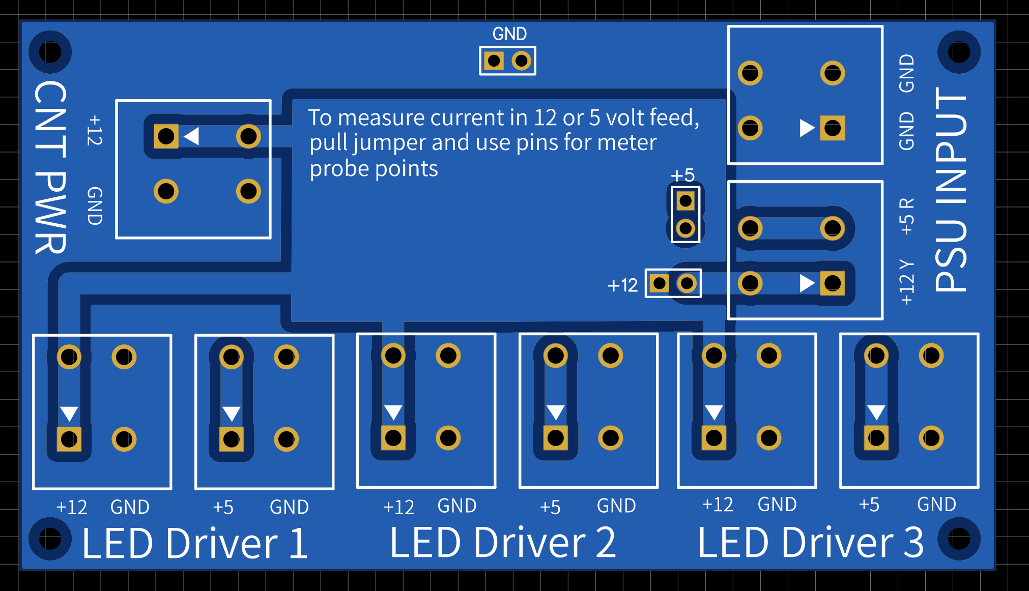
By the way, that blue line that you drew on the graphic is the ground strip that runs along the edge of the PCB. It is electrically equivalent to the ground lines coming from one of the PSUs. But both of the PSUs ground points are ultimately connected together via the pins that drive the base of the TIP141s on each LED driver board. On the graphic you drew the line on, the final resting place of that ground line is the last pin on the connector(s) that drive the base on the TIP141's on every LED panel.
At the top of that graphic, that last solder point is the end pin on those connectors, and as you can see, there are SIX 5-pin connectors at the top of that board and on all six of those connectors, every single pin is electrically equivalent to every other connectors pin of the same number.
So all of the Pin1's on those six connectors are connected together. Same with all of the Pin2's etc. etc. so in that graphic that you drew the blue line on ... where it connects at the top, I would call that Pin5 of the connector that goes out to the TIP141 driver boards and that all six of those connectors are equally grounded at Pin5 (this is what connects the grounds together from both PSUs)
This explains what you ask about in the rest of your quoted response here...
Then as we continue ...
I have not and nor will I remove any of the actual LEDs to try and identify them. But here is a picture of one with its housing removed:

And as I just stated, those could EASILY be 250ma LEDs, which would account for the 5 amps we saw being drawn on the +5 line given the that there could have been 10 sets of these wired in parallel being powered by the PSU. I'll say it again, I think the issue of 5 amps being drawn on the +5 from the PSUs is a dead issue and has been sufficiently explained where that was actually never a problem.
This is how sure I am about that ... when I looked up the actual part number, it indicated that it was some TYPE of regulator where they make them in different flavors, but the datasheet also talked about being able to set the voltage and maybe vary it based on the config layout? I didn't want to spend time learning how to use the regulator, so I just connected power to the 7805 then took voltage readings from the regulator right next to it and it does indeed kick out a steady 3.3 volts.
Also, I just now traced out the 3.3 volt output from that regulator and it stops at one of the pins on the ribbon cable that connects to the LCD display so that must only power the LCD display and not the microcontroller as I previously assumed. Im sure that MC chip is a 5 volt chip as you suggested.
FOR THE RECORD
I think that we can ignore the 5 amps being drawn on the 5 volt line and now focus on the real problem which is the melted +12 wire and the directly connected burn marks on the main controller board.
Originally posted by redwire
View Post
Originally posted by redwire
View Post
The power lines that come in from the PSUs are of course of two types: +5v and +12v
The 5 volt lines ONLY DRIVE LEDs ... the 5 volt lines have NOTHING TO DO with the main controller board OR that wire that melted.
The wire that melted is a tap on the +12 AND GROUND from one of the PSUs, and that wire directly feeds the 7805 that powers the main controller board.
So whatever melted that wire, was from a high current draw on the main controller board. Now that could have been a fan that went bad (as one of them wont power on at all, and it is not shorted either, but I did see that the ground cable on that fan was disconnected at the fan itself and there was some obvious corrosion around those connection points. The wire was soldered onto a PCB at the center of the fan, but it just somehow broke off at the solder point. When I barely tugged on the red wire on that same fan it also came off of its solder point ... since this light assembly sits above a fish tank 24 / 7, moisture is going to be an issue and if its a salt water tank, then that will be even a worse problem.
BUT even though that fan went bad, none of the fan wires were melted or showed any kind of problem at all.
The only damage that we see, is the melted wire, which carries +12 AND GROUND from the PSU to the 7805 on the main controller board. Then on the main controller board, we see burn marks on the PCB directly around the 7805 and also at various points along the GROUND TRACE on the under side of the PCB ...
I want to throw out this thought concerning the +5 and the amperage I saw it taking when I connected the unit to a PSU ...
At that time when I took that reading, I had not taken apart the main unit. So I have no idea which of the two PSU lines inside the unit I was taking that reading from. As one PSU line is split off inside the housing and those lines are connected to TWO LED panels. And those PSU wires go no where else. The other PSU wire connects to the third LED panel but its +12 is tapped to power the main controller board.
Now since +5 ONLY powers LEDs and those LEDs are in parallel, I am suggesting that the amperage we saw might be just fine if we assume that those LEDs can suck a lot of amps... powering 10 sets of two LEDs in parallel (on one PSU and then only 5 sets of parallel LEDs on the other PSU) could add up to 5.5 amps if I was connected to the LED panels that drive 10 sets of two in parallel ... if one set of parallel LEDs consumes only 400ma we're close to 5 amps already. I have LEDs that I can drive safely at 250ma PER LED ... two in parallel is half an amp, then ten of those is 5 amps.
I don't think the +5 amperage issue is of any concern ... the real problem is what happened along that +12 that feeds power to the main controller board - and the evidence for that statement exists in the fact that those wires were melted and there are burn marks on the board that those wires feed. There is no other damage anywhere else in the entire unit. No damage at the LED panels or their driver boards and I did check all of the LED strips and nothing is shorted ... I checked all 15 rows of LEDs and confirmed that they are all working properly.
By the way, that blue line that you drew on the graphic is the ground strip that runs along the edge of the PCB. It is electrically equivalent to the ground lines coming from one of the PSUs. But both of the PSUs ground points are ultimately connected together via the pins that drive the base of the TIP141s on each LED driver board. On the graphic you drew the line on, the final resting place of that ground line is the last pin on the connector(s) that drive the base on the TIP141's on every LED panel.
At the top of that graphic, that last solder point is the end pin on those connectors, and as you can see, there are SIX 5-pin connectors at the top of that board and on all six of those connectors, every single pin is electrically equivalent to every other connectors pin of the same number.
So all of the Pin1's on those six connectors are connected together. Same with all of the Pin2's etc. etc. so in that graphic that you drew the blue line on ... where it connects at the top, I would call that Pin5 of the connector that goes out to the TIP141 driver boards and that all six of those connectors are equally grounded at Pin5 (this is what connects the grounds together from both PSUs)
This explains what you ask about in the rest of your quoted response here...
Originally posted by redwire
View Post
Originally posted by redwire
View Post
And as I just stated, those could EASILY be 250ma LEDs, which would account for the 5 amps we saw being drawn on the +5 line given the that there could have been 10 sets of these wired in parallel being powered by the PSU. I'll say it again, I think the issue of 5 amps being drawn on the +5 from the PSUs is a dead issue and has been sufficiently explained where that was actually never a problem.
Originally posted by redwire
View Post
Also, I just now traced out the 3.3 volt output from that regulator and it stops at one of the pins on the ribbon cable that connects to the LCD display so that must only power the LCD display and not the microcontroller as I previously assumed. Im sure that MC chip is a 5 volt chip as you suggested.
FOR THE RECORD
I think that we can ignore the 5 amps being drawn on the 5 volt line and now focus on the real problem which is the melted +12 wire and the directly connected burn marks on the main controller board.
 CAPs POOF
Comment