Announcement

Collapse
No announcement yet.

LED Driver board Question

Collapse
X
 
  • Filter
  • Time
  • Show
Clear All
new posts

    #21
    Re: LED Driver board Question

    Just one more image to give you an idea of what I'm looking at right now. I took apart the 50 inch panel completely to get at the backlights, so I'm very relieved that the screen seems to be okay.


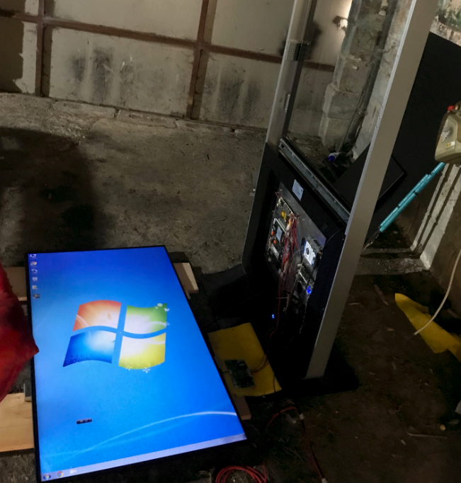
    This is the level of light I get with the 2R2 resistor in place.
    Attached Files

    Comment


      #22
      Re: LED Driver board Question

      its nice set, good candidate for Android / linux TV project instate as store display...LOL

      Comment


        #23
        Re: LED Driver board Question

        Originally posted by Diah View Post
        its nice set, good candidate for Android / linux TV project instate as store display...LOL
        Hah, well you can do that for sure, but I'm downloading Garageband first.

        Comment


          #24
          Re: LED Driver board Question

          Do you have LED tester so you can test and check the Vf of LED strings?
          So it's the Digital Signage display.
          Last edited by budm; 08-12-2020, 01:22 PM.
          Never stop learning
          Basic LCD TV and Monitor troubleshooting guides.
          http://www.badcaps.net/forum/showthr...956#post305956

          Voltage Regulator (LDO) testing:
          http://www.badcaps.net/forum/showthr...999#post300999

          Inverter testing using old CFL:
          http://www.badcaps.net/forum/showthr...er+testing+cfl

          Tear down pictures : Hit the ">" Show Albums and stories" on the left side
          http://s807.photobucket.com/user/budm/library/

          TV Factory reset codes listing:
          http://www.badcaps.net/forum/showthread.php?t=24809

          Comment


            #25
            Re: LED Driver board Question

            "The LEDs in my version of the screen are all at the bottom of the screen, there are two LED strips and each has four parallel sets of 26 LEDs. The back of the panel says 720ma / 78-89V"
            Do you mean that each string has 26 LEDs and 4 of these strings are then connected in parallel?
            Never stop learning
            Basic LCD TV and Monitor troubleshooting guides.
            http://www.badcaps.net/forum/showthr...956#post305956

            Voltage Regulator (LDO) testing:
            http://www.badcaps.net/forum/showthr...999#post300999

            Inverter testing using old CFL:
            http://www.badcaps.net/forum/showthr...er+testing+cfl

            Tear down pictures : Hit the ">" Show Albums and stories" on the left side
            http://s807.photobucket.com/user/budm/library/

            TV Factory reset codes listing:
            http://www.badcaps.net/forum/showthread.php?t=24809

            Comment


              #26
              Re: LED Driver board Question

              I have an LED tester in the post Bud, can't get there here in any shop in Ireland somehow. But it should be here shortly. There's a big digitiser fitted in to the main steel frame - So it's interactive as well. It's actually really cool when it's back together. Would be a hell of a gaming machine if I downloaded the MAME emulator.

              Do you mean that each string has 26 LEDs and 4 of these strings are then connected in parallel?
              4 x 26 LEDs on each strip, and two strips, so total of 8 x 26 LEDs
              Last edited by JonathanAnon; 08-12-2020, 01:36 PM.

              Comment


                #27
                Re: LED Driver board Question

                BTW, did you have a chance to take the Voltage drops reading on that 2R2 resistor at max backlights level so I can verify the power dissipation and current draw?
                Last edited by budm; 08-12-2020, 01:47 PM.
                Never stop learning
                Basic LCD TV and Monitor troubleshooting guides.
                http://www.badcaps.net/forum/showthr...956#post305956

                Voltage Regulator (LDO) testing:
                http://www.badcaps.net/forum/showthr...999#post300999

                Inverter testing using old CFL:
                http://www.badcaps.net/forum/showthr...er+testing+cfl

                Tear down pictures : Hit the ">" Show Albums and stories" on the left side
                http://s807.photobucket.com/user/budm/library/

                TV Factory reset codes listing:
                http://www.badcaps.net/forum/showthread.php?t=24809

                Comment


                  #28
                  Re: LED Driver board Question

                  Hey guys,

                  It's been on for two days solid with the 2R2 resistor. Backlight is more than adequate.

                  Voltage drop on the 2R2 resistor is 200mV

                  Comment


                    #29
                    Re: LED Driver board Question

                    Okay I used my induction ammeter to measure the current as well. There's no obvious location to break the circuit to introduce a series ammeter, so clamp is the best I'm gonna have for the moment.

                    200mV voltage drop across 2R2 resistor. 200mA current on the induction clamp.

                    P=VxI = 0.2V x 0.2A = 0.04 Watts.

                    So, the 2R2 resistor will have to dissipate 40mW.

                    Comment


                      #30
                      Re: LED Driver board Question

                      Originally posted by JonathanAnon View Post
                      Okay I used my induction ammeter to measure the current as well. There's no obvious location to break the circuit to introduce a series ammeter, so clamp is the best I'm gonna have for the moment.

                      200mV voltage drop across 2R2 resistor. 200mA current on the induction clamp.

                      P=VxI = 0.2V x 0.2A = 0.04 Watts.

                      So, the 2R2 resistor will have to dissipate 40mW.
                      Where did you put the Clamp on meter?
                      Post #28 Vdrops 200mV/2R2 = 0.090A = 90mA.
                      Are the reading done at full backlights set to max?
                      Never stop learning
                      Basic LCD TV and Monitor troubleshooting guides.
                      http://www.badcaps.net/forum/showthr...956#post305956

                      Voltage Regulator (LDO) testing:
                      http://www.badcaps.net/forum/showthr...999#post300999

                      Inverter testing using old CFL:
                      http://www.badcaps.net/forum/showthr...er+testing+cfl

                      Tear down pictures : Hit the ">" Show Albums and stories" on the left side
                      http://s807.photobucket.com/user/budm/library/

                      TV Factory reset codes listing:
                      http://www.badcaps.net/forum/showthread.php?t=24809

                      Comment


                        #31
                        Re: LED Driver board Question

                        Originally posted by JonathanAnon View Post
                        Hey guys,

                        It's been on for two days solid with the 2R2 resistor. Backlight is more than adequate.

                        Voltage drop on the 2R2 resistor is 200mV
                        good job.. this change will be better than the original second R332
                        you have edge LED double cell ,, not much will happen as the set store display., back light are working on one level and the 2R will be protect to PWB.

                        Comment


                          #32
                          Re: LED Driver board Question

                          Originally posted by budm View Post
                          Where did you put the Clamp on meter?
                          Post #28 Vdrops 200mV/2R2 = 0.090A = 90mA.
                          Are the reading done at full backlights set to max?
                          I put the clamp on the two positive wires coming out of the driver board feeding the LED strips. Does seem low to me but that is what it reads.

                          Sorry Bud, I meant to say this - there is no means for the user to change the backlight through brightness setting or the like. There is no remote control. So the backlight current will be fixed.

                          Comment


                            #33
                            Re: LED Driver board Question

                            LOL.. some user may don't Know or missed to read this threat carefully.. this is STORE DISPLAY

                            Comment


                              #34
                              Re: LED Driver board Question

                              Originally posted by JonathanAnon View Post
                              I put the clamp on the two positive wires coming out of the driver board feeding the LED strips. Does seem low to me but that is what it reads.

                              Sorry Bud, I meant to say this - there is no means for the user to change the backlight through brightness setting or the like. There is no remote control. So the backlight current will be fixed.
                              They probably have it set to about 90% PWM which is typical for Signage Display, which is still high and that is why the resistor burn out.
                              Never stop learning
                              Basic LCD TV and Monitor troubleshooting guides.
                              http://www.badcaps.net/forum/showthr...956#post305956

                              Voltage Regulator (LDO) testing:
                              http://www.badcaps.net/forum/showthr...999#post300999

                              Inverter testing using old CFL:
                              http://www.badcaps.net/forum/showthr...er+testing+cfl

                              Tear down pictures : Hit the ">" Show Albums and stories" on the left side
                              http://s807.photobucket.com/user/budm/library/

                              TV Factory reset codes listing:
                              http://www.badcaps.net/forum/showthread.php?t=24809

                              Comment


                                #35
                                Re: LED Driver board Question

                                Originally posted by budm View Post
                                They probably have it set to about 90% PWM which is typical for Signage Display, which is still high and that is why the resistor burn out.
                                don't find excuse for wrong statement.. this Edge LED back light double cell, this why i asked him if there was wrong,,but OP clarified its Edge.

                                now about Edge.. did you asked your self why here no much threat about this type ?

                                allot of answer here.. start from the Freq. to currents.. to circuit .. OP upload photos easy to 2R2 & R332 are NOT sensing current but to just protect the PWB LED section.

                                Comment


                                  #36
                                  Re: LED Driver board Question

                                  Originally posted by Diah View Post
                                  don't find excuse for wrong statement.. this Edge LED back light double cell, this why i asked him if there was wrong,,but OP clarified its Edge.

                                  now about Edge.. did you asked your self why here no much threat about this type ?

                                  allot of answer here.. start from the Freq. to currents.. to circuit .. OP upload photos easy to 2R2 & R332 are NOT sensing current but to just protect the PWB LED section.
                                  How many time are you going to making fools of yourself.
                                  1) Do you understand what constant current circuit does and how it maintain constant current through the LED's?

                                  2) As you can see, pin 3 of the IC U1 is monitoring the Vdrops on the resistor, if the Vdrops staring to change, it means the current through the LED is changing, so pin 3 of the IC is sensing that Vdrops to maintain the current at set level by changing the PWM that drive the power MOSFET Q7,.
                                  when current is constant, the Vrops will be constant.
                                  To maintain something at constant, you need feed loop, any person that knows electronics will understand that.

                                  3) Did you look up the spec sheet of U1 to find out what that IC is for? I bet you did not and that is why you do not understand the circuit. I ask OP for the P/N and did the research so I can see how this board works.

                                  4) So you are saying if you put LED light source on the edge, instead of backlit, the LED driver circuit for maintaining current is not the same topology? Who teach you that?
                                  Attached Files
                                  Never stop learning
                                  Basic LCD TV and Monitor troubleshooting guides.
                                  http://www.badcaps.net/forum/showthr...956#post305956

                                  Voltage Regulator (LDO) testing:
                                  http://www.badcaps.net/forum/showthr...999#post300999

                                  Inverter testing using old CFL:
                                  http://www.badcaps.net/forum/showthr...er+testing+cfl

                                  Tear down pictures : Hit the ">" Show Albums and stories" on the left side
                                  http://s807.photobucket.com/user/budm/library/

                                  TV Factory reset codes listing:
                                  http://www.badcaps.net/forum/showthread.php?t=24809

                                  Comment


                                    #37
                                    Re: LED Driver board Question

                                    OP:
                                    I did not start the fight.
                                    Never stop learning
                                    Basic LCD TV and Monitor troubleshooting guides.
                                    http://www.badcaps.net/forum/showthr...956#post305956

                                    Voltage Regulator (LDO) testing:
                                    http://www.badcaps.net/forum/showthr...999#post300999

                                    Inverter testing using old CFL:
                                    http://www.badcaps.net/forum/showthr...er+testing+cfl

                                    Tear down pictures : Hit the ">" Show Albums and stories" on the left side
                                    http://s807.photobucket.com/user/budm/library/

                                    TV Factory reset codes listing:
                                    http://www.badcaps.net/forum/showthread.php?t=24809

                                    Comment


                                      #38
                                      Re: LED Driver board Question

                                      If I swop the 2R2 for a 1 ohm resistor and measure the current will that settle the argument

                                      Comment


                                        #39
                                        Re: LED Driver board Question

                                        Originally posted by budm View Post
                                        OP:
                                        I did not start the fight.
                                        there is no fight.. it is KNOW HOW

                                        Comment


                                          #40
                                          Re: LED Driver board Question

                                          Originally posted by Diah View Post
                                          there is no fight.. it is KNOW HOW
                                          LOL!

                                          I am not going to waste OP times and thread.
                                          Never stop learning
                                          Basic LCD TV and Monitor troubleshooting guides.
                                          http://www.badcaps.net/forum/showthr...956#post305956

                                          Voltage Regulator (LDO) testing:
                                          http://www.badcaps.net/forum/showthr...999#post300999

                                          Inverter testing using old CFL:
                                          http://www.badcaps.net/forum/showthr...er+testing+cfl

                                          Tear down pictures : Hit the ">" Show Albums and stories" on the left side
                                          http://s807.photobucket.com/user/budm/library/

                                          TV Factory reset codes listing:
                                          http://www.badcaps.net/forum/showthread.php?t=24809

                                          Comment

                                          Working...
                                          X