Thank you to the guys at HEGE supporting Badcaps [ HEGE ] [ HEGE DEX Chart ]

Announcement

Collapse
No announcement yet.

AeroCool VP-550 : IC identification issue

Collapse
X
 
  • Filter
  • Time
  • Show
Clear All
new posts

    AeroCool VP-550 : IC identification issue

    Hi there,

    A few years ago, my ATX Aerocool VP-550 blew its fuse. I replaced it : it blew again...

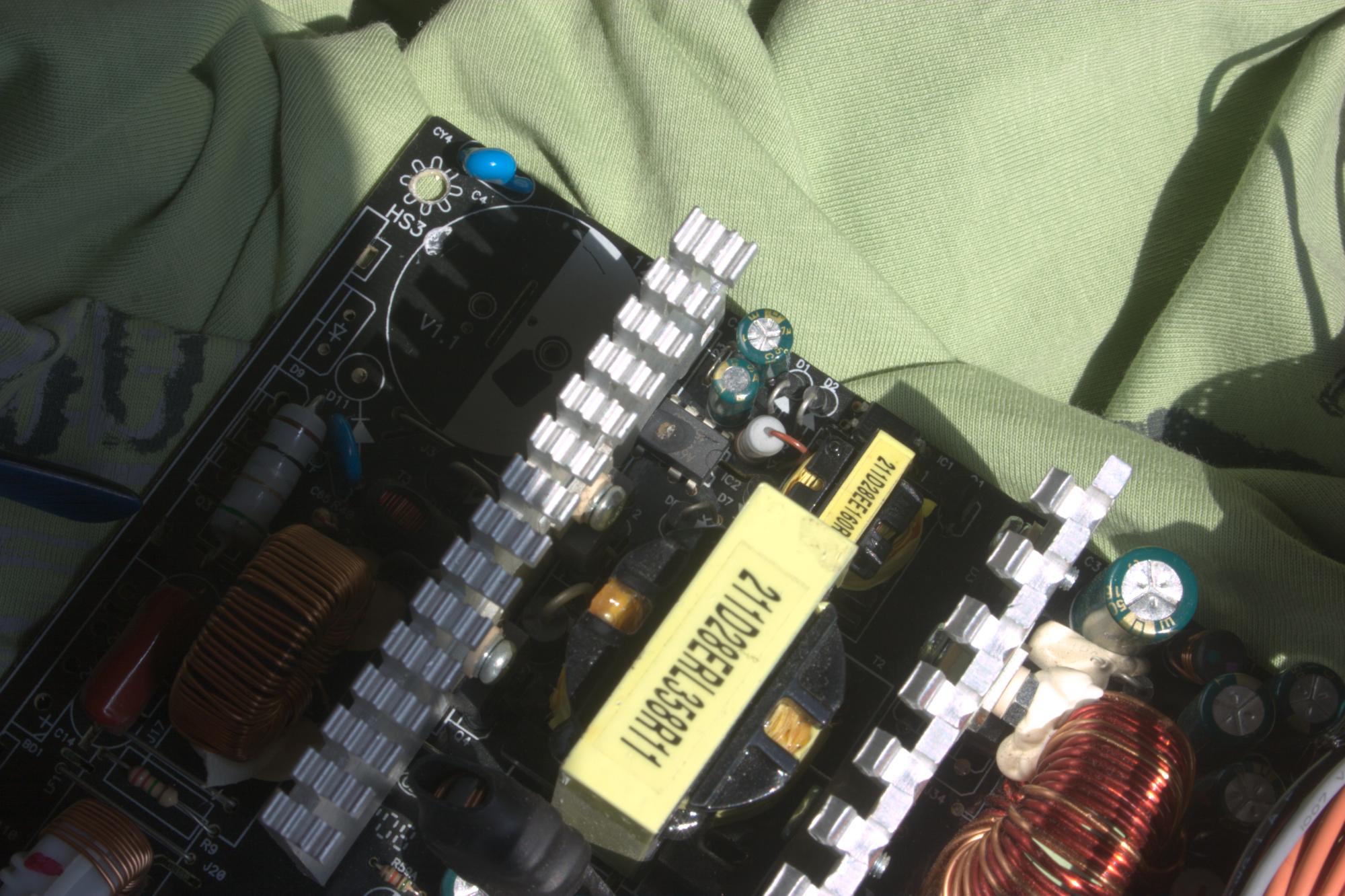
    A IC blew as well, and is now showing it guts (see center of the picture).

    After some research, I think it belongs to the STR-A6000 series (Off-Line PWM Controllers with Integrated Power MOSFET).
    I can see its first 2 digits "A6...."

    It has only 7 pins instead of 8 (no pin 6)
    It's located very close to the filter capacitor (180uF, 400V) of the primary stage.

    Does someone know what IC it is exactly ?

    Other components out-of-order (maybe more...) :
    • thermistor SCK-2R56 (2.5 ohms, 6A)
    • Bridge rectifier GBU606 (short)
    • Capacitor (180uF, 400V) shows 5.5uF on digital multimeter
    • unknown IC (STR-A6000 series?)
    • MOSFET MDP13N50 (sits just next to the bridge rectifier on the same heatsink, short)


    Attached Files
    Last edited by SMDFlea; 04-03-2023, 09:16 AM. Reason: Added image to badcaps from external link

    #2
    Re: AeroCool VP-550 : IC identification issue

    Hopefully you were careful opening the case. The rest of the lid of the IC should be floating around the inside of the power supply. I think you are right on it being a Sanken STR-A60xx series. Luckily there aren’t many to choose of. However these very few to choose of have different switching frequency. 67 vs 100khz.
    Last edited by CapLeaker; 04-03-2023, 03:42 PM.

    Comment


      #3
      Re: AeroCool VP-550 : IC identification issue

      Originally posted by CapLeaker View Post
      Hopefully you were careful opening the case. The rest of the lid of the IC should be floating around the inside of the power supply. I think you are right on it being a Sanken STR-A60xx series. Luckily there aren’t many to choose of. However these very few to choose of have different switching frequency. 67 vs 100khz.
      Unfortunately, I didn't pay attention while opening the case, and the rest of the IC is lost...

      As for the exact part number, I ordered a few STR-A6059H (the first of the series working at 100kHz), thinking maybe it was related to another IC on the other side of the PCB : a CM6805BG (10-PIN Green-Mode PFC/PWM Combo CONTROLLER), which also works at 100kHz.

      There's certainly a way to determine, or at least narrow down the research, to find which one would fit knowing the other components connected to it but I don't know how and I couldn't find a place where to order a complete STR-A6000 series.

      Probably Vdss MIN(V) and Rds(on) MAX (ohm) of the IC can give some important information to choose wisely...

      Thanks for your reply.

      Comment


        #4
        Re: AeroCool VP-550 : IC identification issue

        Nope. That’s not how the PSU works. There are 2 parts to it. One part is always on and that’s the part this Sanken offline Switcher does. Then there is the PWM / PFC and that is your main power supply, plus the supervisor IC on the secondary.
        Look up the Powerman IP that I repaired. My bet is that not only this offline Switcher is bad, the main filter cap (400V) is probably toast too. While you are at it, change each cap near a heatsink too.

        Comment


          #5
          Re: AeroCool VP-550 : IC identification issue

          Originally posted by CapLeaker View Post
          Nope. That's not how the PSU works. There are 2 parts to it. One part is always on and that's the part this Sanken offline Switcher does. Then there is the PWM / PFC and that is your main power supply, plus the supervisor IC on the secondary.
          Look up the Powerman IP that I repaired. My bet is that not only this offline Switcher is bad, the main filter cap (400V) is probably toast too. While you are at it, change each cap near a heatsink too.
          Oh ok, I thouht these 2 ICs were related. I know now they aren't.

          So, if the STR-A6059H I ordered fits well (fingers crossed...) and replacing the thermistor, the bridge rectifier, the MOSFET and the unique filter capacitor (180uF, 400V, reads only 5.5uF with the multimeter), I should see +5V on PS-ON and +5V on STAND BY, right ?
          (I should probably better try with a bulb in series first...)

          There's indeed another IC on the other side of the PCB which controls PFC : CM6805BG (10 pins, surface mounted). Well, I think that's the one who does this.

          There's indeed also a supervisor IC : HY-510N in the secondary part.

          You mean my PS is bad ? Possible, I'm not a pro...
          Do you mean replacing ALL caps that sits next to a heatsink, even small ones !?!? (I suppose you talk about electrolytic caps only...)

          But I remember seeing a beautiful spark while connecting the 4 pins CPU connector and I think my motherboard has suffered since then...And that any even new PS connected to it suffers...
          I had to buy a third power supply, which also suffered, and I can't use my PC since a few years (I had to manually short the green and black wire to start it, and then push on the start button of my PC, really weird...). In short, a big mess...

          I've seen your post about your Power Man : f... capacitor...
          Well, I already know mine is out : reads 5.5uF instead of 180uF with my DMM

          Thanks for your reply.
          Last edited by bendeg; 04-04-2023, 08:26 AM.

          Comment


            #6
            Re: AeroCool VP-550 : IC identification issue

            What do you think of such fuse holder in a PC power supply ?
            1. Ok, no problem
            2. No way !
            3. At your own risks !

            In fact, I don't really trust that kind of holder : inner springs might be loose over time...


            Comment


              #7
              Re: AeroCool VP-550 : IC identification issue

              Wrong way of testing things. Make a jig called a dim bulb tester. Works only with incandescent (old style) light bulbs. Get a 60w, a 100W and a 150w or 200w bulb. Otherwise you still risk that you blow parts up that you just put in.

              Comment


                #8
                Re: AeroCool VP-550 : IC identification issue

                Originally posted by CapLeaker View Post
                Wrong way of testing things. Make a jig called a dim bulb tester. Works only with incandescent (old style) light bulbs. Get a 60w, a 100W and a 150w or 200w bulb. Otherwise you still risk that you blow parts up that you just put in.
                Ok, thanks for the advice !

                Comment


                  #9
                  Re: AeroCool VP-550 : IC identification issue

                  Originally posted by CapLeaker View Post
                  Hopefully you were careful opening the case. The rest of the lid of the IC should be floating around the inside of the power supply. I think you are right on it being a Sanken STR-A60xx series. Luckily there aren't many to choose of. However these very few to choose of have different switching frequency. 67 vs 100khz.

                  I've received the STR-A6059H (working at 100kHz), and ready to be soldered, but I think it may not be a good idea (I've ordered 6 others of the series, mainly those that works at 67kHz, but 2 others that works at 100kHz as well, a bit crazy but I must try...) :

                  Let's suppose the proper IC should work at 67kHz, it such a case it means it also expects modulation feedback that would not match if I put one that works at 100kHz, right ?

                  In a nutshell, in such a case, the "modulation time" of the feedback would be too long with the STR-A6059H and the IC would work almost twice as much time, maybe at 100%, overwhelming the circuit. See what I mean ?

                  It would be the other way round if I put a 67kHz one intead of a chip that should work at 100kHz ?

                  Am I wrong ? Or is the feedback automatically "sensed" ?

                  Comment


                    #10
                    Re: AeroCool VP-550 : IC identification issue

                    I did some digging (being bored this morning ) and I found one single reference on the AeroCool VP-550 that chip in question being an STR-A6069H.

                    Good luck!

                    Comment


                      #11
                      Re: AeroCool VP-550 : IC identification issue

                      Yes, in these series is STR-A6069H.
                      Attached Files

                      Comment


                        #12
                        Re: AeroCool VP-550 : IC identification issue

                        Originally posted by CapLeaker View Post
                        I did some digging (being bored this morning ) and I found one single reference on the AeroCool VP-550 that chip in question being an STR-A6069H.

                        Good luck!
                        As I see in the datasheet A6059H has the same specs (it would probably be a good replacement IC)

                        But how the hell did you find that !?!?

                        Thank you so much !!!

                        Comment


                          #13
                          Re: AeroCool VP-550 : IC identification issue

                          Originally posted by lotas View Post
                          Yes, in these series is STR-A6069H.
                          It's a slightly different configuration (there's a second capacitor near the heatsink and there's no what looks like a yellow capacitor close to pin 3 and 4)

                          But anyway, thank you so much !!!

                          I also plan to install a 8 pins socket so IC can be replaced easily if needed.

                          Keep you all updated once I've got all parts soldered.
                          Fingers crossed...

                          Comment


                            #14
                            Re: AeroCool VP-550 : IC identification issue

                            Originally posted by bendeg View Post
                            As I see in the datasheet A6059H has the same specs (it would probably be a good replacement IC)

                            But how the hell did you find that !?!?

                            Thank you so much !!!
                            By not using Google as a search engine. Yw.!
                            Using a 6069H or a 6059H doesn’t matter. The Difference is the max input voltage handling of the IC.
                            Last edited by CapLeaker; 04-11-2023, 04:21 AM.

                            Comment


                              #15
                              Re: AeroCool VP-550 : IC identification issue

                              Originally posted by CapLeaker View Post
                              By not using Google as a search engine. Yw.!
                              Using a 6069H or a 6059H doesn't matter. The Difference is the max input voltage handling of the IC.
                              Indeed, I only tried google search...

                              Oh, ok, it'll be the A6069H or any A606x then (700V max), not the A6059H (650V max).

                              Thank you very much for that info !

                              Comment


                                #16
                                Re: AeroCool VP-550 : IC identification issue

                                Originally posted by bendeg View Post
                                I also plan to install a 8 pins socket so IC can be replaced easily if needed.
                                Don't!

                                The Source and Drain pins on the IC (mostly the Drain pins) are used as a heatsink. If you install on a socket, the chip will likely overheat and die faster.

                                Solder it in, instead.

                                Make sure to also replace that failed primary cap. This is likely the reason the IC blew in the first place. With APFC circuits, if the main cap fails, a nasty high-voltage spike will appear downstream on the primary side. Sometimes it kills nothing and PSU just blows the fuse on the input. Other times, it can kill the APFC MOSFETs, main PS MOSFETs, or even the 5VSB / standby offline switch IC (STR-A6069H in your case.)

                                My personal suggestion is to also put a polypropylene cap in parallel with the mains cap, so in case of a failure of the big cap again, the PP cap can take some of the energy / high-voltage spike and be less likely to end up with other dead components. Use a PP cap between 0.1 to a few uF, rated for 450V minimum (630V better.)

                                Lastly, use a dim bulb tester when testing the 5VSB with the replaced IC. 60-100 Watts incandescent or halogen will do. Once 5VSB function is verified, you can test the PSU with a slightly bigger halogen bulb in series - 200-300 Watts... or hair dryer on the "low" setting.

                                Comment


                                  #17
                                  Re: AeroCool VP-550 : IC identification issue

                                  Originally posted by momaka View Post
                                  Don't!

                                  The Source and Drain pins on the IC (mostly the Drain pins) are used as a heatsink. If you install on a socket, the chip will likely overheat and die faster.

                                  Solder it in, instead.

                                  Make sure to also replace that failed primary cap. This is likely the reason the IC blew in the first place. With APFC circuits, if the main cap fails, a nasty high-voltage spike will appear downstream on the primary side. Sometimes it kills nothing and PSU just blows the fuse on the input. Other times, it can kill the APFC MOSFETs, main PS MOSFETs, or even the 5VSB / standby offline switch IC (STR-A6069H in your case.)

                                  My personal suggestion is to also put a polypropylene cap in parallel with the mains cap, so in case of a failure of the big cap again, the PP cap can take some of the energy / high-voltage spike and be less likely to end up with other dead components. Use a PP cap between 0.1 to a few uF, rated for 450V minimum (630V better.)

                                  Lastly, use a dim bulb tester when testing the 5VSB with the replaced IC. 60-100 Watts incandescent or halogen will do. Once 5VSB function is verified, you can test the PSU with a slightly bigger halogen bulb in series - 200-300 Watts... or hair dryer on the "low" setting.
                                  1)

                                  Fortunately, STR-6069H hasn't been delivered yet. Thank you for the advice !

                                  And indeed, as I can read in the datasheet, page 23, for pin 7 (I believe this is what you want to tell me...) :
                                  "
                                  (7) Thermal Considerations
                                  Because the power MOSFET has a positive thermal
                                  coefficient of R DS(ON) , consider it in thermal design.
                                  Since the copper area under the IC and the D/ST pin
                                  trace act as a heatsink
                                  , its traces should be as wide as
                                  possible.
                                  "

                                  2)
                                  I already planned to change the main cap (JunFu, 180uF, 400V, 85°, LG, 25mm x 40mm snap-in) : my DMM shows only 5.5uF instead of 180uF...

                                  I have 2 different new caps replacement:
                                  • Nichicon, 180uF, 400V, 105*, PT(M), 18mm x 40mm
                                  • Nichicon, 180uF, 450V, 105°, GG(M), 25mm x 40mm snap-in and fits perfectly (same size as original)


                                  Is this a problem to put the first one (18mm x 40mm) ? Should the size match the original perfectly ?

                                  3)
                                  polypropylene cap : you mean a capacitor that looks like a yellow X2 capacitor or that looks more like a woman handbag, a brown purse like this one :

                                  4)
                                  You mean that if a test with a 60-100W bulb in series pass with the new IC, I should try with 200-300W bulb afterwards or an hair dryer ??? Not sure I understand that part, do you mean connecting a hair dryer on the "low" setting in series with the PSU ?
                                  I don't have a hair dryer but I have a small 500-600W hand mixer (in the kitchen) with a turbo button (a "normal" button and a "turbo" button), that might work as well :-D

                                  I knew for the test with a bulb of about 60-100W, but not more, why is that needed ? To test little by little to make sure nothing wrong happens ?
                                  Last edited by bendeg; 04-12-2023, 08:23 AM.

                                  Comment


                                    #18
                                    Re: AeroCool VP-550 : IC identification issue

                                    Originally posted by bendeg View Post
                                    1)

                                    Fortunately, STR-6069H hasn't been delivered yet. Thank you for the advice !

                                    And indeed, as I can read in the datasheet, page 23, for pin 7 (I believe this is what you want to tell me...) :
                                    "
                                    (7) Thermal Considerations
                                    Because the power MOSFET has a positive thermal
                                    coefficient of R DS(ON) , consider it in thermal design.
                                    Since the copper area under the IC and the D/ST pin
                                    trace act as a heatsink
                                    , its traces should be as wide as
                                    possible.
                                    "
                                    Yes, this is exactly the reason.

                                    Originally posted by bendeg View Post
                                    2)
                                    I already planned to change the main cap (JunFu, 180uF, 400V, 85°, LG, 25mm x 40mm snap-in) : my DMM shows only 5.5uF instead of 180uF...

                                    I have 2 different new caps replacement:
                                    • Nichicon, 180uF, 400V, 105*, PT(M), 18mm x 40mm
                                    • Nichicon, 180uF, 450V, 105°, GG(M), 25mm x 40mm snap-in and fits perfectly (same size as original)


                                    Is this a problem to put the first one (18mm x 40mm) ? Should the size match the original perfectly ?
                                    Use the 450V cap.

                                    For the primary cap, bigger is always better - both in terms of size and capacity. This is one part where manufacturers save the most money by using parts that are just adequate enough for the power rating of the PSU at the expense of the part not lasting as long.

                                    Since the 450V cap fits perfectly in terms of size, use that. It should last a lot longer than the original.
                                    Better yet, if you can get an bigger cap (say, 220 uF) to fit and if it doesn't cost significantly more, that would be nice too. But don't sweat it too much. Looks like you already found a cap that fits and rated for a higher voltage, which is even better.

                                    I try not to use anything lower than 420V -rated caps for PSUs with APFC circuits. 400V caps just seem to not last in certain APFC circuits.

                                    Originally posted by bendeg View Post
                                    3)
                                    polypropylene cap : you mean a capacitor that looks like a yellow X2 capacitor or that looks more like a woman handbag, a brown purse like this one :
                                    Use the "woman handbag" one... and LOL! That's actually a pretty accurate visual description, I like it.
                                    Just make sure it is Polypropylene (PP) type. Polyester (PE) can look the same... and for the most part, it's still a film capacitor and will work mostly the same. However, PP has better frequency response and is the one recommended for high-frequency circuits.

                                    I don't know if I can recommend X2, since it's mostly for AC input filter applications, and here on the APFC we are dealing with high-voltage DC (with small HF AC ripple.)

                                    Originally posted by bendeg View Post
                                    4)
                                    You mean that if a test with a 60-100W bulb in series pass with the new IC, I should try with 200-300W bulb afterwards or an hair dryer ??? Not sure I understand that part, do you mean connecting a hair dryer on the "low" setting in series with the PSU ?
                                    Install new IC and test with 60-100W bulb in series with the PSU, like this:
                                    https://www.badcaps.net/forum/showpo...51&postcount=6
                                    https://www.badcaps.net/forum/showpo...4&postcount=70

                                    The 60-100W bulb is only when you want to test if the PSU outputs 5VSB. Once you want to test the entire PSU (by connecting PS_ON to ground), you will need to replace the 60-100W bulb with something more powerful, because of the APFC circuit. APFC does not like high-impedance paths on it's supply input, which is what the 60-100W will be at the high frequency that the APFC circuit pulses its MOSFETs to primary ground. What will likely happen with the 60-100W bulb if you try to power-on the PSU (PS_ON to ground) is the bulb will likely flash on-and-off very quickly or just stay lit continuously and not let the PSU start.

                                    For this reason, you connect a higher-power linear device, such as hair dryer, toaster, heat gun (non-digital one)... or just 4+ 60-100 Watt incandescent or halogen bulbs in parallel (4x 60W bulbs in parallel = 240 Watts equivalent.)

                                    Originally posted by bendeg View Post
                                    I don't have a hair dryer but I have a small 500-600W hand mixer (in the kitchen) with a turbo button (a "normal" button and a "turbo" button), that might work as well :-D
                                    Mixer probably won't work, since it has a motor inside. You want a device / appliance with some sort of heating element and simple On-Off switch control (i.e. no digital circuits or "soft" push-buttons.)

                                    If you don't have such appliance, just use incandescent or halogen bulbs. I know that in EU it's harder to get these now. If that's the case and you can't find such higher-power bulbs, use 40W incandescent "appliance" type bulbs - these are regular incandescent bulbs, but they work the same. EU can't ban these, because appliances such as your kitchen oven can't use LED or CFL bulbs inside it - they simply won't last. So "appliance" incandescent bulbs are exempt from the incandescent bulb ban.

                                    Originally posted by bendeg View Post
                                    I knew for the test with a bulb of about 60-100W, but not more, why is that needed ? To test little by little to make sure nothing wrong happens ?
                                    Pretty much, yes.
                                    60-100W for testing the 5VSB.
                                    200-300W or more for testing whole PSU (PS_ON connected to ground.)

                                    That being said, beware that some PSUs won't work without a small load on the output. You may have to connect an HDD or two or three... or a 12V halogen bulb on the 12V/5V rails. In such case, however, just know that the higher the load you put on the output of the PSU, the bigger the power rating of the series incandescent/halogen bulb will need to be on the input.

                                    IME, the limit is usually around 20-25% of the power of the series bulbs - i.e., if you use a 300W halogen bulb on the input of the PSU, you may be able to pull only about 60-75W of power on the output. This is for PSUs without APFC. With APFC, the dynamic can change a little... but assuming 20-25% again is a pretty safe bet.
                                    Last edited by momaka; 04-12-2023, 10:15 AM.

                                    Comment


                                      #19
                                      Re: AeroCool VP-550 : IC identification issue

                                      Originally posted by momaka View Post
                                      ...
                                      Oh, that's a lot of information.

                                      There's more to do now...I'll update this thread when I've got all the components.

                                      Thank you very much !!!

                                      Comment


                                        #20
                                        Re: AeroCool VP-550 : IC identification issue

                                        What is the power rate of that 5 bands resistor (1 stage, near the big capacitor) ?

                                        I couldn't find a color code calculator that found the answer using 5 bands.
                                        Looks like it's a 4 bands resistor with a fifth one...

                                        According to its color, BROWN - BLACK - SILVER - GOLD - GREEN...
                                        (correct me if I'm wrong, I'm color blind, I've got problems especially with the greens, I'm a "deuteranope" guy)

                                        ...it's a 4 bands resistor, and it should be a 0.1 Ohm 5% resistor, right ? (and indeed, I can measure it with my DMM).

                                        Then, if it's a 4 bands resistor, what is the meaning of the last green band ?

                                        Also, how can I find the power rating so I could order one if needed (even if it looks in good shape to my eyes) ?
                                        Dimensions : width = ~17mm, diameter = ~6mm
                                        Is it a 5W resistor ? More than 5W ?
                                        Attached Files
                                        Last edited by bendeg; 04-26-2023, 02:13 AM.

                                        Comment

                                        Working...
                                        X