New Design: Helper Board for Video Head Units

Collapse
X
 
  • Time
  • Show
Clear All
new posts
  • ratdude747
    Black Sheep
    • Nov 2008
    • 17136
    • USA

    #1

    New Design: Helper Board for Video Head Units

    Over the last several years I've had Android head units in my truck (1995 Ranger), there's been some issues that have always bugged me... or I solved in a less than "ideal" manner. I've designed/ordered PCBs and ordered parts for a board to hopefully fix all of these in a better way, and I'd like to share the design here.

    Attached is a .zip of the KiCAD files, Schematic, Gerber Files, and BOM from digikey (ok, it's a downloaded excel of my order I placed, close enough...)

    The issues this board corrects are (and what I currently am doing that sucks):
    1. This provides a power-off delay via a diode and capacitor; due to the fact that these units don't automatically pause when ignition power drops (heck, the touchscreen is still active!), this gives one several seconds after key-off to pause one's tunes. Otherwise, it will keep playing music in the background until the sleep timer kicks in and shuts down android. Not cool! Right now I have a 330uf 35V cap and a diode soldered into the harness; it's what I had at the time in the junk pile.
    2. Adds capability for a second power-on (ignition) input. No plans to do such, but adding it here was trivial (1 extra diode), and I had a terminal to spare.
    3. Relay isolates the reverse camera trigger signal. On my current unit, I've fought it for some time; my trigger isn't a "crisp" 0V->12V (it floats a lot), and without any correction, the head unit would randomly trigger the reverse camera screen (which blanks the screen and kills all physical switches/knobs). I've tried all sorts of resistor divider, diode isolation w/ pulldown, zener diode clipper, and opticoupler circuits but residual feedback/float would cause issues. Right now I have it in a steep resistor divider (1/3 ratio if memory serves), which mostly corrected the issue, but if reverse kicks on during bootup, the button lockout occurs until reverse is triggered again. I'm fed up with having to flash reverse to unlock my head unit at stoplights, and honestly this is why I am finally getting around to this project
    4. Eliminates all current harness splices in my setup. To facilitate this, two ground terminals on the vehicle side are provided (since I'm using an RCA adapter for my audio, which feeds the factory amp). The Antenna/Amp signal is routed through the board to allow for such, and the terminals and (hopefully) the power/ground fill areas are rated for the 15A the head unit maxes at (fuse rating).
    5. Eliminates the solder splices in the reverse camera cable. Due to the way my reverse camera is made (and the craptastic RCA plug they used), there used to be crimp splices on my RCA camera cable to allow it to enter the firewall via an existing grommet (for the shift cable). Those crimps failed, and I soldered it... and re-soldered it when I moved to a different Ranger. A short female-female RCA cable is needed to interface the board with the RCA jack on the board. No idea how well this will work; I didn't impedance analyze the relevant portion of the board (but I did via stitch the shield planes at least). I've seen composite video work on sketchier setups... we shall see. EDIT: Short RCA cables don't exist pre-made, but male-male couplers exist, which in my case, will work (if memory serves, my camera input is on a pigtail). Worst case I use a longer cable and coil it... or cut and re-plug it.


    Mounting: I didn't put any mounting holes in the design... I was planning on hot gluing some plastic sheeting to the bottom of the board (cut from some junk clamshell packaging or the like) and letting it hang in the stereo bay. Or velcro it to the top of the head unit; in my case, I have room to do so.

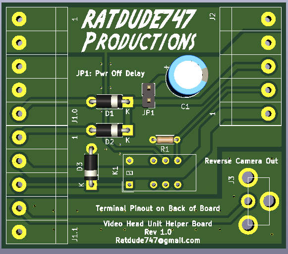
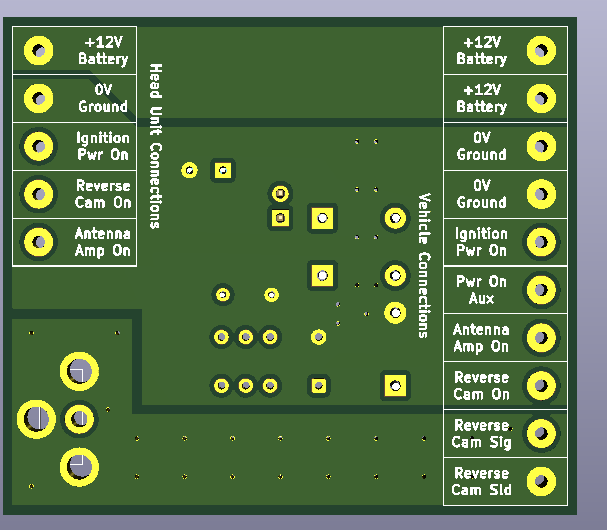
    Screenshots of the board design:


    Hopefully the boards and parts will come in soon... and then I can give her a spin.
    Attached Files
    Last edited by ratdude747; 05-19-2020, 09:56 PM.
    sigpic

    (Insert witty quote here)
  • Curious.George
    Badcaps Legend
    • Nov 2011
    • 2305
    • Unknown

    #2
    Re: New Design: Helper Board for Video Head Units

    Originally posted by ratdude747
    The issues this board corrects are (and what I currently am doing that sucks):

    This provides a power-off delay via a diode and capacitor; due to the fact that these units don't automatically pause when ignition power drops (heck, the touchscreen is still active!), this gives one several seconds after key-off to pause one's tunes. Otherwise, it will keep playing music in the background until the sleep timer kicks in and shuts down android. Not cool! Right now I have a 330uf 35V cap and a diode soldered into the harness; it's what I had at the time in the junk pile.
    Is there not an input or other signal on the head unit that you can use to effectively "turn it off"? Your hack seems to just let you realize you forgot to shut it off before killing the ignition (?) (does "POWERON_OUT" actually POWER something -- hence the need for such a big cap)

    Relay isolates the reverse camera trigger signal. On my current unit, I've fought it for some time; my trigger isn't a "crisp" 0V->12V (it floats a lot), and without any correction, the head unit would randomly trigger the reverse camera screen (which blanks the screen and kills all physical switches/knobs). I've tried all sorts of resistor divider, diode isolation w/ pulldown, zener diode clipper, and opticoupler circuits but residual feedback/float would cause issues. Right now I have it in a steep resistor divider (1/3 ratio if memory serves), which mostly corrected the issue, but if reverse kicks on during bootup, the button lockout occurs until reverse is triggered again. I'm fed up with having to flash reverse to unlock my head unit at stoplights, and honestly this is why I am finally getting around to this project
    Note that -- unless you use a mercury-wetted relay -- the REVERSE_OUT signal will likely show some contact bounce. Whether this will be "seen" depends on what is LOOKING at the signal. If a problem, you can add a little filter on the REVERSE_OUT signal so it doesn't react to the closing relay contact quite as quickly.

    Eliminates all current harness splices in my setup. To facilitate this, two ground terminals on the vehicle side are provided (since I'm using an RCA adapter for my audio, which feeds the factory amp). The Antenna/Amp signal is routed through the board to allow for such, and the terminals and (hopefully) the power/ground fill areas are rated for the 15A the head unit maxes at (fuse rating).
    You can figure out the current carrying capacity from the width of the foils and the weight of the copper clad. (I didn't look at your Gerbers as that's on another computer).

    Eliminates the solder splices in the reverse camera cable. Due to the way my reverse camera is made (and the craptastic RCA plug they used), there used to be crimp splices on my RCA camera cable to allow it to enter the firewall via an existing grommet (for the shift cable). Those crimps failed, and I soldered it... and re-soldered it when I moved to a different Ranger. A short female-female RCA cable is needed to interface the board with the RCA jack on the board. No idea how well this will work; I didn't impedance analyze the relevant portion of the board (but I did via stitch the shield planes at least). I've seen composite video work on sketchier setups... we shall see. EDIT: Short RCA cables don't exist pre-made, but male-male couplers exist, which in my case, will work (if memory serves, my camera input is on a pigtail). Worst case I use a longer cable and coil it... or cut and re-plug it.
    I'm not sure I completely follow the gender designations -- you mentioned F-F then M-M. You can buy RCA female-female adapters: https://www.amazon.com/Electop-RCA-F.../dp/B01CJ5SCGW

    Mounting: I didn't put any mounting holes in the design...
    Been there, done that. That's why they invented revision numbers!! :<

    Comment

    • ratdude747
      Black Sheep
      • Nov 2008
      • 17136
      • USA

      #3
      Re: New Design: Helper Board for Video Head Units

      Originally posted by Curious.George
      Is there not an input or other signal on the head unit that you can use to effectively "turn it off"? Your hack seems to just let you realize you forgot to shut it off before killing the ignition (?) (does "POWERON_OUT" actually POWER something -- hence the need for such a big cap)
      Such is is the power-on signal... corresponds to the ignition-on signal provided my most vehicles. If anything is directly powered off of it (LCD/Button backlights?), I wouldn't know. 330uf works decently (gives about 5 seconds of power-on after killing the ignition), so my logic is 470 will give me a bit more time to pause before killing ignition power.


      Originally posted by Curious.George
      Note that -- unless you use a mercury-wetted relay -- the REVERSE_OUT signal will likely show some contact bounce. Whether this will be "seen" depends on what is LOOKING at the signal. If a problem, you can add a little filter on the REVERSE_OUT signal so it doesn't react to the closing relay contact quite as quickly.
      I thought about that... but given how picky the input is about logic levels, I was afraid such's rounding off of the signal on the off-swing would cause more harm than good (Read: same issue as I already have). If I have issues, I'll add a small cap in parallel with the pulldown resistor. Easy bodge and design change.

      Originally posted by Curious.George
      You can figure out the current carrying capacity from the width of the foils and the weight of the copper clad. (I didn't look at your Gerbers as that's on another computer).
      I know... however, the fills aren't rectangular, and I couldn't be bothered to mess with it. I just went with my gut. The +12V side is two identical large fills, which I am reasonably confident will work fine. The GND planes in the middle of the board are a different situation; I routed all traces on the top of the board, making the bottom plane uninterrupted other than for solder pads. The top has a deep cut where the 12V power trace comes in to feed the relay contact; I surrounded it with some via stiching to make the top plane a bit more useful in carrying current. As wide as the plane is, the bottom alone should be sufficient I'd think.


      Originally posted by Curious.George
      I'm not sure I completely follow the gender designations -- you mentioned F-F then M-M. You can buy RCA female-female adapters: https://www.amazon.com/Electop-RCA-F.../dp/B01CJ5SCGW
      You missed it. Yes, I did mean male-male (like a normal cable)... as the head unit (pigtail or jack on board) gives a female end, and so does my boards. Digikey doesn't stock jacks with male ends... they're all female. Hence why I went for a male-male adapter since I already have a 6" pigtail on the head unit.

      Originally posted by Curious.George
      Been there, done that. That's why they invented revision numbers!! :<
      We'll see. The "smart" way to do this would be to perfboard a prototype before spinning a PCB design, but as relatively cheap as these boards are ($24 shipped for 5), I'm willing to gamble on it.
      sigpic

      (Insert witty quote here)

      Comment

      • Curious.George
        Badcaps Legend
        • Nov 2011
        • 2305
        • Unknown

        #4
        Re: New Design: Helper Board for Video Head Units

        Originally posted by ratdude747
        Such is is the power-on signal... corresponds to the ignition-on signal provided my most vehicles. If anything is directly powered off of it (LCD/Button backlights?), I wouldn't know. 330uf works decently (gives about 5 seconds of power-on after killing the ignition), so my logic is 470 will give me a bit more time to pause before killing ignition power.
        So, there's a significant "load" on that cap causing it to discharge pretty quickly. As voltage drop per-unit-time is linearly proportional to capacitance (CV=It), you can expect a factor of 470/330 increase in "hold over" time... so, about 7 seconds, total.

        I thought about that... but given how picky the input is about logic levels, I was afraid such's rounding off of the signal on the off-swing would cause more harm than good (Read: same issue as I already have). If I have issues, I'll add a small cap in parallel with the pulldown resistor. Easy bodge and design change.
        Or, look for a mercury-wetted relay in the same pinout!

        You missed it. Yes, I did mean male-male (like a normal cable)... as the head unit (pigtail or jack on board) gives a female end, and so does my boards. Digikey doesn't stock jacks with male ends... they're all female. Hence why I went for a male-male adapter since I already have a 6" pigtail on the head unit.
        Ah, OK. I thought you were having a male pigtail "dangling" off your board and wanting it to mate with another male coming from the camera.

        We'll see. The "smart" way to do this would be to perfboard a prototype before spinning a PCB design, but as relatively cheap as these boards are ($24 shipped for 5), I'm willing to gamble on it.
        I've learned that it's usually not worth the hassle of breadboarding -- if you're going to want a REAL board, sooner or later. "Prototype in foil" and plan on doing at least one revision before KNOWING what you really want. If you get lucky and can "patch" the first set of boards (to skip the revision), then that's just a bonus!

        Good luck!

        [BTW, make sure the relay "holding voltage" is at least 8V as you can expect the battery to drop to that level while cranking]

        Comment

        • ratdude747
          Black Sheep
          • Nov 2008
          • 17136
          • USA

          #5
          Re: New Design: Helper Board for Video Head Units

          Originally posted by Curious.George
          So, there's a significant "load" on that cap causing it to discharge pretty quickly. As voltage drop per-unit-time is linearly proportional to capacitance (CV=It), you can expect a factor of 470/330 increase in "hold over" time... so, about 7 seconds, total.
          Exactly.

          Originally posted by Curious.George
          [BTW, make sure the relay "holding voltage" is at least 8V as you can expect the battery to drop to that level while cranking]
          Its 9V... Not that it matters, since I won't be cranking in reverse!
          sigpic

          (Insert witty quote here)

          Comment

          • ratdude747
            Black Sheep
            • Nov 2008
            • 17136
            • USA

            #6
            Re: New Design: Helper Board for Video Head Units

            A bit belated, but I got boards... and some issues happened.

            The board itself works OK... the issue is the head unit itself and some missed conveniences:

            -Forgot to account for the parking brake wire, which I have tied to ground. To make it more universal, the next board (if there is one) will have a pass through with a selection jumper.
            -Forgot the illumnination wire... passthrough.
            -Capacitor placement didn't agree with the terminal strips. Stupid 45 degree design... I should have known better.
            -Still have the reverse input issue... seems the issue is in the MCU itself. I even tried NC'ing it to ground (and bodging the existing setup to flip the contact polarity)... no bueno.

            What I wish I had was a head unit output that would kick on whenever the bootup was complete. I don't have that; the amp/antenna seems to follow the ignition input. Such would give me a way (via a 555 pulse circuit or the like) to force the reverse input on momentarily at bootup, and also would allow me a better way to deal with another quirk; for my USB OBD2 adapter to work with torque, I have to power cycle it (which I do via a on-off per port USB hub mounted in the side of the glove box). Instead, I could route the USB through the board (not hard since KICAD has a differential pair tool) and use both contacts of another micro relay and run it to a 12V switch that I'd mount in the dash (an I/O reset switch of sorts). Not an elegant solution, but without an existing output to follow (and the boot time not being repeatable, sometimes it hangs for several minutes), it's the option I have if I want to go there. Which I probably will, when I have time to redesign such.
            sigpic

            (Insert witty quote here)

            Comment

            • ratdude747
              Black Sheep
              • Nov 2008
              • 17136
              • USA

              #7
              Re: New Design: Helper Board for Video Head Units

              Drew up a new board. Haven't ordered it or parts yet; It's bed time and I'll nail it tomorrow.

              Features added/changed:

              -Has illumination and parking brake passthough (with grounding jumper)
              -Has I/O reset input and USB passthough. USB data tracks routed as differential pair (matched lengths) but isn't impedance matched, but for the USB1.1 speeds that OBDII adapters run at, it should be OK?
              -Changed to right angle terminals. Same price, but uses less space and can carry more current (not that I needed the latter, but it's nice to have buffer!)
              -Radically redid layout and terminal arrangement to allow for mounting on the back of the top of the head unit.
              -+12V power traces *should* be able to run 15A per some rough calculations (did each track at 7.5A through the 7pcb calculator, a hair above minimum). removed solder mask on bottom trace that I can tin heavily to give more safety factor (I doubt I'm drawing close to 15A; but that's what the head unit is fused for).

              Images and a .zip of the source files, schematic PDF, and gerber files attached.

              Any suggestions are welcome.
              Attached Files
              sigpic

              (Insert witty quote here)

              Comment

              Related Topics

              Collapse

              • Tynan Dill
                Vizio e601i-A3 - Has Sound and Display, But No Backlight - Bad Power Supply Board or Bad LED Bulbs ?
                by Tynan Dill
                I was given this TV from my great uncle. He said it just wouldn't turn on one day out of nowhere, replaced the TV, and gave it to me to possibly fix and use for myself.

                Upon bringing it home and plugging it up, it showed a standby light.

                I powered it on and without a flashlight, the display showed the "V" but the lighting is very dim, but visible.

                The screen seems to blackout and stay black, but with a flashlight I can see the display.

                With my Playstation 4 connected via HDMI, and running a game I can hear sound.

                Assuming...
                11-22-2024, 01:46 PM
              • m1ch43lzm
                HP Pavilion 15-eh Board DAG7HAMB8F0 - CPU throttling to 0.4GHz (PROCHOT_EXT) and black screen
                by m1ch43lzm
                Hi, this is my personal laptop, which the original board (lets call it Board A) blew up PU8700 (TPS51486), making a hole on the board, i had left the laptop at my desk one day with the battery fully charged and didn't touch it for a week, but when i tried to turn it on it didn't
                Thought the battery was dead, so i plugged in the charger then tried to power on, the power LED blinked once, charged LED still orange, unplugged the charger, plugged in again and I noticed the "magic smoke" smell, so i unplugged the charger, removed the back cover and saw the blown IC (the "magic...
                05-12-2025, 08:37 PM
              • howardc64
                A1312 (27” iMac 2009-2011) A1407 (Thunderbolt Display) A1316 (Cinema Display) Display Black Screen Repair
                by howardc64
                Problem

                This is an LG edge LED lit LCD Display. The LEDs are on the bottom edge of the display. There are 2 bars (left and right) Each bar has many LEDs and a 6 pin connector. Each pin drive several LEDs thus is the highest current flow / heat junction. The weak lead free solder gradually fails with thermal expansion/contraction cycling and increases resistance. PSU will compensate up to a point, then when the current is too high, PSU just shut down the backlight causing a dark display. I have even seen one which the connector just fell off as solder points became completely detached....
                08-04-2024, 10:36 PM
              • FeerBaron
                Got in way over my head with Supermicro server board and upgrade.
                by FeerBaron
                Last year I bought a server. It's worked fairly well but had some issues. Some pcie slots didn't work and Xeon v4 is a bit slow and missing AVX 512. Came to realize that the next version up, with skylake uses mostly the same chassis.

                A board popped up on ebay one day being sold for parts. A working board like this is over a grand at best. This particular one was about $125 and I decided to gamble.

                At first it seemed simple enough. According to the description it looked like some mechanical damage.


                Found the missing 560uf cap and thought I was...
                Starts
                01-26-2024
                Ends
                01-26-2024
                01-26-2024, 06:36 AM
              • Hakuu
                LG OLED77G1PUA - No Video / Audio after a TCON Board change and Software Update
                by Hakuu
                Hi There,

                This TV was auto switching off after few seconds with some vertical lines on the screen, so got a new TCON board and replaced it.

                After replacing the TCON board it was working fine and i set it up with everything, used for few hours, then had the bright idea to update the software on it. During the update process, TV switched off and now no audio or video. No relay switch sound.

                More Details

                TV Model - LG OLED77G1PUA

                Got the same exact TCON board from TVPartsToday and replaced it. But didnt transfer the EPPROM data (didnt...
                07-12-2023, 02:37 PM
              • Loading...
              • No more items.
              Working...