![]() |
|
|
Thread Tools |
![]() |
#1701 | |
Member
Join Date: Jun 2015
City & State: eastern province
My Country: saudi arabia
I'm a: Knowledge Seeker
Posts: 51
|
![]() Quote:
Photo: 
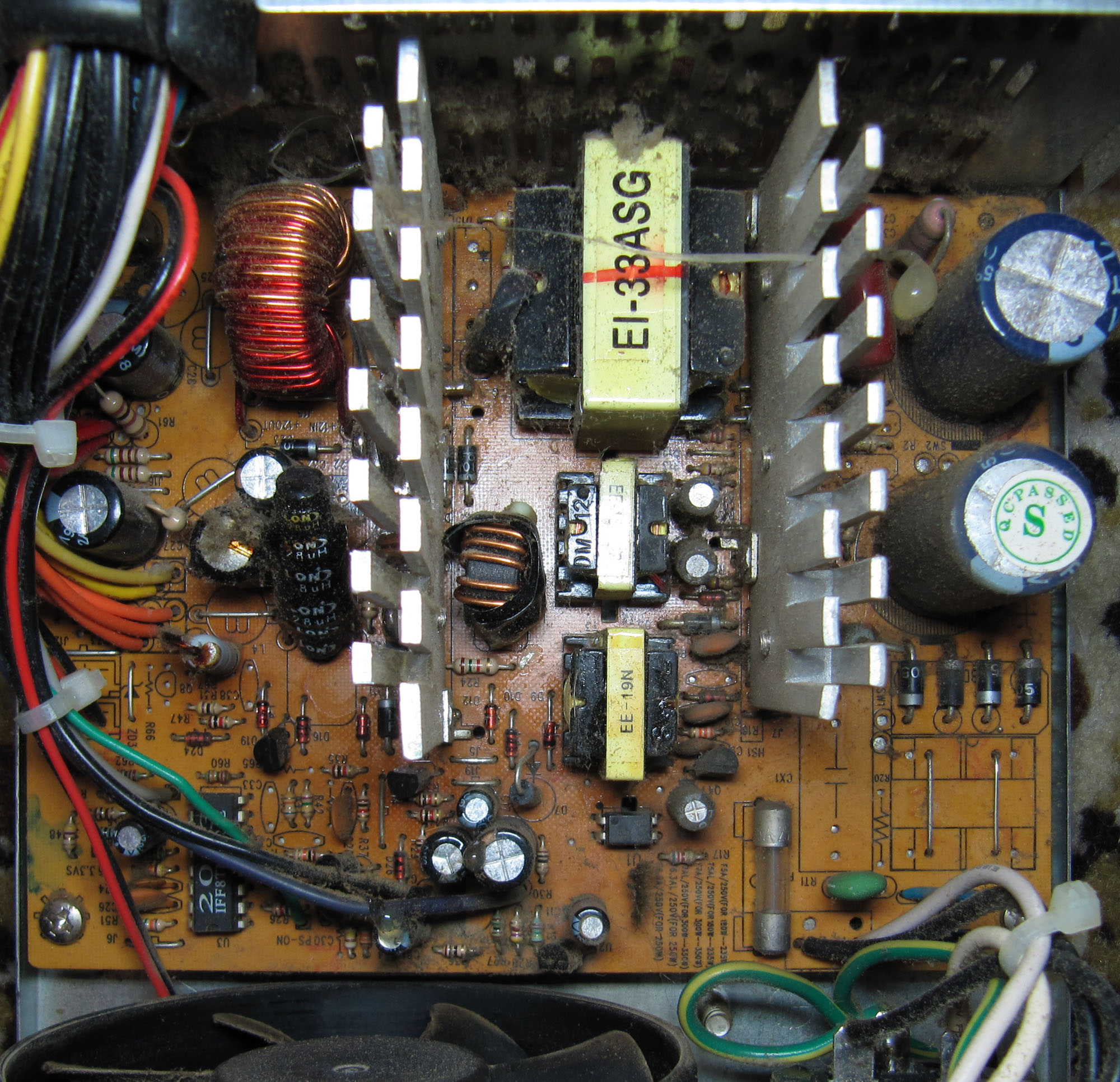
My friend has an old PC with quadcore intel and was working fine and being used by his son for online schooling. Yesterday, it suddenly failed without warning, no power at all even manually shorting from the 24pins (green and black). I checked and opened the PSU because there was no output at all. Surprised the fuse was still intact after tested it. Tested the primary diodes and all are good. It has very similar lay-out of the PCB for this generic and cheap PSU and even using similar rectifier diodes and arrangement of other electronic parts. I already confirmed the cheap PSU is the culprit because i tried another PSU and the PC works fine. What could be the problem if fuse is still intact? Does it mean the primary winding is good and i should concentrate more on secondary? I want to learn how to fix this PSU and not because it is cheaply made but because i am seeking further knowledge. I will try to open it up again tonight and see if i can find something on the board Last edited by rayfloyd170; 01-30-2022 at 05:41 AM.. |
|
![]() |
![]() |
![]() |
#1702 |
SNES-powered
Join Date: Oct 2013
City & State: Bacau
My Country: Romania
Line Voltage: 230VAC 50Hz
I'm a: Hobbyist Tech
Posts: 1,471
|
![]() I would trash it and replace it with a cheap FSP or Delta unit, especially since it's a quad core Intel. Those are hungry when it comes to power.
__________________
Main rig: Gigabyte B75M-D3H Core i5-3470 3.60GHz Gigabyte Geforce GTX650 1GB GDDR5 16GB DDR3-1600 Samsung SH-224AB DVD-RW FSP Bluestorm II 500W (recapped) 120GB ADATA + 2x Seagate Barracuda ES.2 ST31000340NS 1TB Delux MG760 case |
![]() |
![]() |
![]() |
#1703 | |
Member
Join Date: Jun 2015
City & State: eastern province
My Country: saudi arabia
I'm a: Knowledge Seeker
Posts: 51
|
![]() Quote:
Yeah already replaced with antec 350 and working good. i just want to learn how to fix this kind of prob and was thinking this is a good start to troubleshoot. i have nothing to lose and everything to gain. I would like to add, there is minimal hissing sound somewhere when plugged to the mains but i cannot pinpoint it. also voltage can be detected in primary but nothing in secondary. I am suspecting the mosfets and i need to remove them and test. i also found a semi-cold solder for one diode 1N5822 and tested it and found to be okay and resoldered it well. Last edited by rayfloyd170; 01-30-2022 at 11:24 PM.. |
|
![]() |
![]() |
![]() |
#1704 | |
master hoarder
Join Date: May 2008
City & State: VA (NoVA)
My Country: U.S.A.
Line Voltage: 120 VAC, 60 Hz
I'm a: Hobbyist Tech
Posts: 10,862
|
![]() Quote:
And if you do fix the PSU... DON'T connect it to a computer anymore. It's a really low-end unit with high ripple/noise output and will probably damage parts over time. You can use it to power LEDs, motors, and other non-sensitive items on your workbench, though. Lastly: that PSU looks like a Deer/Allied/L&C unit, so it can actually be turned into something... less garbage. But you will need to fill in a lot of the missing parts (output PI coils, input common-mode chokes, input X2-caps, input Y2-caps) and upgrade the cheap parts in there (2x 2200 uF caps for each output rail, 2x 470 uF 200V input caps minimum, and etc.) |
|
![]() |
![]() |
![]() |
#1705 | |
Member
Join Date: Jun 2015
City & State: eastern province
My Country: saudi arabia
I'm a: Knowledge Seeker
Posts: 51
|
![]() Quote:
Thanks for the valuable inputs, and for safety. I am just trying to learn the basic of fixing psu's. This photo is for reference only and not the actual photo of the PSU i am trying to repair. The actual psu has been reliably working for more than 10 years and suddenly gave up. Impressive!!! yeah given it is cheaply made. On the other hand, I have confirmed that the 2 main caps 330uF/200V are faulty. Initially i only get 120V from the primary and supposed to have 220-240V. This prompted me to check the main caps. One has 0 uF and the other 275uF so way beyond the spec. I will try to replace them and see what happens. I have checked all diodes by removing them and also all major resistors/ small caps by removing them individually and all are good except a few that need new ones. If this thing works then i learn something. Last edited by rayfloyd170; 01-31-2022 at 03:20 AM.. |
|
![]() |
![]() |
![]() |
#1706 |
Badcaps Veteran
Join Date: Oct 2009
City & State: Thessaloniki, Greece
My Country: Greece
Line Voltage: 230VAC 50Hz
I'm a: Knowledge Seeker
Posts: 2,137
|
![]() Those are quite expensive, so your desire to learn trying to fix this psu will cost you a lot. In my opinion you should start collecting broken devices and parts inluding psus (ATX or not doesn't matter) and before you even know you will have everything you need to be able to play and experiment and maybe even build/fix something that will be of value to you after.
If you were in Greece I could give you many junk psus to play/use for parts. You could try to get them from people giving away broken stuff for free or dirt cheap or from recycle bins (of electronics), if this is allowed where you live. Did you check the fuse of the psu to see if it's blown? I would also check recification diodes, and primary main transistors. Might be blown from the open primary cap |
![]() |
![]() |
![]() |
#1707 | |
Member
Join Date: Jun 2015
City & State: eastern province
My Country: saudi arabia
I'm a: Knowledge Seeker
Posts: 51
|
![]() Quote:
Yes, already checked them all before and all are good. Yesterday I replaced the 2 main caps with Rubycon 330uF 250V ( was expensive and i am not expecting the cost from local parts store) and also 1 transistor due to open caps as you mentioned. And now it was working, couldnt believe it. I wouldnt mind as long as i learn. thank you all for the tips. Last edited by rayfloyd170; 01-31-2022 at 11:18 PM.. |
|
![]() |
![]() |
![]() |
#1708 |
CapXon Be Gone
Join Date: Sep 2011
City & State: Idaho
My Country: USA
Line Voltage: 120VAC 60Hz
I'm a: Hardcore Geek
Posts: 3,216
|
![]() I can't believe it but this power supply completely fried!!
![]() ![]() https://www.badcaps.net/forum/showpo...postcount=1618 The main output toroid core turned white and the wire is pitch black. It even fried a 12.5mm Chemicon KY and a Samxon RS! Above the Ky cap: Here's the story: It was made in August 2005, recapped in October 2013 and immediately installed afterwards. It ran 24/7 and was powering the following: Pentium 4 641 (3.40GHz, D0 version = 65W TDP), which had the 15A rated 12V rail all to itself x4 DDR1 RAM Radeon HD 4350 x1 DVD drive x2 PCI cards (WiFi and Sound card) x1 3.5" HDD x2 fans It ran with this setup for about 60,000 hours before it failed. When you attempted to turn it on, you'd get a twitch on the PSU fan and about 3 seconds of spinning on the CPU fan. It was used to stream football/TV so the P4 was pushed pretty hard. It was online, so super inefficient on the CPU compared to local x264 files. I believe maybe the toroid just wasn't enough for this PSU? The silicon was very strong for the ratings. Label: Silicon: 5V: Two 30A TO-247 schottky 12V1 (Non CPU): Two 10A ultra fast 12V2 (CPU): Two 20A schottky 3.3V: 40A TO-247 schottky What do you think happened? I have a hard time believing that the load killed it, especially with a Cedar Mill P4 and super low power GPU. What I did also notice was a partially stripped wire on an extra cable touching the chassis. I imagine that this would have just tripped the protection and shut it down, not fry it?? What are your thoughts? This is very sad because this was a nice PSU and I don't really have the extra time to find a toroid for it. |
![]() |
![]() |
![]() |
#1709 |
Super Moderator
Join Date: Jul 2005
City & State: ----
My Country: Sweden
Line Voltage: 230v 50Hz
I'm a: Knowledge Seeker
Posts: 5,116
|
![]() These types of failures are always caused by overheating.
I have only seen it when the fan or fan controller failed...
__________________
"The one who says it cannot be done should never interrupt the one who is doing it." |
![]() |
![]() |
![]() |
#1710 | ||
master hoarder
Join Date: May 2008
City & State: VA (NoVA)
My Country: U.S.A.
Line Voltage: 120 VAC, 60 Hz
I'm a: Hobbyist Tech
Posts: 10,862
|
![]() Quote:
![]() That's a really surprising failure, for sure. I agree, I don't think the load should have killed it. Cedar Mills are still Pentium 4 CPUs, but relatively more tame in terms of TDP. If yours is indeed the 65W TDP version and not the 86W version (specs of the two can be found here), then that CPU peaks at almost 80W on absolute max power (generally synthetic benchmarks only.) With a heavy online load, it's probably using somewhere around its rated TDP or maybe a little more... so let's say 70-75W. Looking at the pictures of the PSU again, I see the output toroid has a yellow core, suggesting Micrometals -26 type core, which is good for up to 50 KHz designs and also slightly less efficient compared to the green core with blue paint on one side (Micrometals -52.) What I also see is that your output toroid is about as tall as the UCC KY 16V, 3300 uF cap, and that's a 35 mm tall cap (the UCC KY is sitting flush to the PCB, I presume, whereas the output toroid isn't... hence why it looks a little taller, but it probably isn't.) This leads me to believe the output toroid is a T130-26 part... which should indeed be perfectly capable for the 350 Watt rating on the label. In fact, T130-26 could handle designs up to 450-500 Watts... maybe even 550 Watts. It's a pretty chunky core after all. That said, I don't think I can quite identify what the issue is here. Seems like multiple things. It could be... 1) The output toroid's core overheated due to inadequate ventilation / airflow from the fan or the fan controller, as Per suggested. More precisely, I can see the following possible scenarios: -- 1a) Thermistor is improperly placed to keep the PSU cool under high load. I notice from this picture that the thermistor for the fan controller is connected to the heatsink, but very far away from the components that generate the heat - i.e. the 12V rail rectifiers and the output toroid itself. -- 1b) Fan controller is not designed properly - i.e. it doesn't ramp up the fan speed enough for the heat from the PSU. -- 1c) The output toroid could be in a "hot spot", given that this PSU uses an overhead 120 mm fan and the secondary heatsink covers the output toroid almost completely. (On that note, this is one reason I tend to still prefer the old PSU designs with cross-airflow from an 80 mm exhaust fan and airy front vents.) In regards to all of the above for item 1), I think 1a) and 1b) can be ruled out if you ever checked how the PSU ran under load in a PC - i.e. was the whole case of the PSU hot? If not, then that leaves 1c) as the more probable cause here. 2) There was a flaw with the output toroid. Things such as micro-cracks in the core material or marginal insulation on the windings, can show up as a latent failure. In the case of micro-cracks, the core/inductor will work at first, but excessive heat may form around the area with the micro-cracks. Over time, the micro-cracks can grow (due to heating in those parts), causing more heat and inefficiency, and thus total failure from overheating at some point. In the case of windings with marginal insulation - regular vibration from components inside the computer (fans, HDDs, optical drives, and etc.) as well as one-time "step" vibrations (walking in the room where the PC is, bumping the PC by accident, and etc.) could have caused a short-circuit to develop somewhere... and it only takes one shorted turn. Case in point: the Corsair CX750M I posted in this thread: https://www.badcaps.net/forum/showthread.php?t=99159 ^ Apparently, that PSU was working "OK" for a while... and then it failed. If you do have the time to read through that thread, you might even find some useful information about output inductors. In fact, I've obtained/bought several different types of output toroids and plan on testing them to see if I can revive that PSU. ![]() 3) Maybe either the UCC KY or the Samxon RS had a random failure? ![]() 4) Bad output filter design. I also find this to be highly unlikely... but again not impossible. What I mean by "bad output filter design" is that perhaps the capacity of the output caps was underestimated in the design, thus leading to higher spike currents in the output core. Or perhaps the output toroid didn't have enough turns on its core? ![]() https://www.badcaps.net/forum/showthread.php?t=85301 ^ From these two BFG PSUs, the 1st one worked OK, but the 2nd one had a burned output toroid (due to fan failure - fans run "too fast" in these PSUs and the fans bite the dust... literally.) Both of these use the "larger" T130-26 toroid just like this Macron PSU. However, note how much more copper wire/turns there are on the output inductor compared to your Macron PSU. For the one with the burned toroid, I didn't have a replacement T130-26 toroid, so I used a smaller T106-26 toroid from a crappy 235W JNC/Meico PSU I scrapped over a decade ago. I haven't load-tested the "fixed" BFG PSU too extensively, since I recapped it with crappy leftover caps. It did pass a 50-60W load test, though. Fortunately, I have found a source of replacement cores now! ![]() Quote:
https://www.badcaps.net/forum/showpo...postcount=2230 ... and what I found is that just with a 72 Watt load, the output toroid in that PSU was running at close to 60C. Of course, that was in the summer with 30C room temperature (or thereabouts.) Nonetheless, further cross-load testing increased the temperature of the output toroid even more. And with a basic Pentium 4 Northwood 2.8 GHz PC (1 HDD, onboard video, and such), I could feel the whole PSU's case was really really warm to the touch. ![]() ![]() ![]() Anyways... if you do decide you want to try to fix your Macron PSU, and not by taking an output toroid from another PSU but doing a complete "scratch" build... there are replacement cores available. T130-26 can be found here: https://www.ebay.com/itm/25455766419...gAAOxy63FSsJH1 For T106-26 (which you don't need to replace in your PSU... but just mentioning it here for anyone else that might), I couldn't find an exact replacement, but I found T106-26b, which is a core with the same inner and outer diameters, but thicker... so may need a bit of experimenting with the number of turns, possibly: https://www.ebay.com/itm/26178786367...UAAOSwPYZU6bO- And the seller from the two listings above also has a T131-26 core, which is essentially a T130-26, but with much thicker core, therefore having smaller inner hole diameter... which again may require adjustment to the # of turns to get the right inductance. But if you feel experimental, this is it: https://www.ebay.com/itm/25188712105...EAAOSw34FVDIET Anyways, I do plan on updating the threads for my Corsair CX750M and the BFG Tech PSUs... when I get to them (hopefully soon - I'm dealing with a crap ton of Samsung TV's I've been finding lately at just about every corner of every street, and I really want to get at least some of them going and out of the house - they take soooo much space!) Last edited by momaka; 02-13-2022 at 12:24 AM.. |
||
![]() |
![]() |
![]() |
#1711 | |
Badcaps Veteran
Join Date: Aug 2005
City & State: San Jose, CA
My Country: USA, Unsure of Planet
Line Voltage: 120VAC, 60Hz & 115VAC, 400Hz
I'm a: Professional Tech
Posts: 3,384
|
![]() Quote:
If you try rebuilding that output inductor, I suggest using -52 material, which is the same permeability and, IIRC, lower loss, even at a “low” switching frequency (e.g. 30 KHz).
__________________
PeteS in CA Power Supplies should be boring: No loud noises, no bright flashes, and no bad smells. **************************** To kill personal responsibility, initiative or success, punish it by taxing it. To encourage irresponsibility, improvidence, dependence and failure, reward it by subsidizing it. **************************** Anti-Covid-Vaxxer pig crap claim/prediction, Doctor: Heart Failure from mRNA Jabs "Will Kill Most People" | Principia Scientific Intl. ; Dr. Geert Vanden Bossche Warns COVID-19 Jab Injuries and Deaths Will Soon "Collapse Our Health System" (VIDEO) ; Fully Vaxxed May 2021; Since that time I've done 7 5Ks, 1 8K, 8 10Ks, and 4 half marathons Last edited by PeteS in CA; 02-13-2022 at 05:59 PM.. |
|
![]() |
![]() |
![]() |
#1712 | |
CapXon Be Gone
Join Date: Sep 2011
City & State: Idaho
My Country: USA
Line Voltage: 120VAC 60Hz
I'm a: Hardcore Geek
Posts: 3,216
|
![]() Quote:
![]() I might take you up on your offer to rewind it! If I don't end up sending it to you. I have plenty of power supplies but I appreciate your offer ![]() |
|
![]() |
![]() |
![]() |
#1713 |
Badcaps Veteran
Join Date: Aug 2005
City & State: San Jose, CA
My Country: USA, Unsure of Planet
Line Voltage: 120VAC, 60Hz & 115VAC, 400Hz
I'm a: Professional Tech
Posts: 3,384
|
![]() Except with vacuum tubes, heat is seldom a friend in electronics.
|
![]() |
![]() |
![]() |
#1714 |
Solder Sloth
Join Date: Nov 2012
City & State: CO
My Country: USA
Line Voltage: 120VAC 60Hz
I'm a: Hobbyist Tech
Posts: 7,156
|
![]() Well, even vacuum tubes can take so much before frying.
And then we find a tcxo... heh. |
![]() |
![]() |
![]() |
#1715 | |
Badcaps Veteran
Join Date: Aug 2005
City & State: San Jose, CA
My Country: USA, Unsure of Planet
Line Voltage: 120VAC, 60Hz & 115VAC, 400Hz
I'm a: Professional Tech
Posts: 3,384
|
![]() Quote:
It is also possible to overload vacuum tubes and cause them to overheat. |
|
![]() |
![]() |
![]() |
#1716 |
A Fake Rubycon
Join Date: Jan 2017
City & State: Peoples Republic of California
My Country: USA
Line Voltage: 122.5VAC 59.9Hz
I'm a: Knowledge Seeker
Posts: 673
|
![]() So here is a PSU i just found at Goodwill today, A few things about it caught my attention, which is why i'm posting it so soon after getting it (and why i may have picked it up in the first place).
Anyway, Here is a case overview: IMG_20220313_190631293.jpg Looks pretty standard, we have a 80mm fan on the front and a 90mm fan on the top, you can also see the goodwill price tag, with how much i paid for this thing (and in a moment, we will find out if it was worth it (spoilers if you read the thread name)). Label: IMG_20220313_190649936.jpg So at first, this looked like just a normal aftermarket PSU label to me, but as i looked at it longer, more and more things stood out to me, first, i was looking at the rated current of each rail, and noticed that the overall 12v1 and 12v2 rail currents was lower than the 5v rails rated current, which is odd since this is a fairly modern PSU. But it gets worse, as at the bottom of the label it says "12v1 and 12v2 total output 20A" which puts the total maximum 12v rails output at 240w, which is still a bit higher than the total 5v + 3.3v rail current, but not as high as other modern PSUs. It also says this unit was designed by Topower. While i don't know a lot about Topower, i'm willing to somewhat bet that they had no say in this PSU design. And lastly, the wire color list on the label is incorrect for all the rails except 5v, 12v1 and 2, -12v, and ground, which is one of the funnier ones to me. And now time to see what's inside, with a board overview: IMG_20220313_191916393.jpg IMG_20220313_191929177.jpg Wow, don't know what to say, other than its not looking good so far. I like the fact that the felt the need to bodge a wire in parallel with the ground trace, as clearly, this thing would be so powerful that it would melt that trace without that bodge. You can also see a few hotspots on the PCB, mainly around the 5VSB/Aux power supply parts of the PSU. Primary side: IMG_20220313_192149471.jpg IMG_20220313_192200167.jpg Okay, so for input filtering, we have a sloppy looking common mode choke, and two 2.2nf 2Kv ceramic capacitors where a pair of Y-class capacitors should be, but other than that, there is basically no input filtering or PFC. The rectifier is a KBL406G (4A, 600v), and we have a mismatch pair of 470uf 200v capacitors (Jay'long and Chang, both test at roughly 340uf). The main switcher is a K3569, controlled by a 3842B (looks like they're trying to spoil us by giving us something other than the usual dual forward design ![]() Secondary side: IMG_20220313_192212462.jpg The filtering for each real is as follows; (and every capacitor is a Cheng LOWESR cap unless stated otherwise) 5VSB: SBL3040PT rectifier (30A! 40V. With one leg cut off!), 2x 470uf 16v with a PI coil between them. 12V: MBR20100CT rectifier (20A, 100V), 1500uf 25v with no PI coil. 5V: SBL1640CT rectifier (16A, 40V), 2200uf with no PI coil. 3.3V (Which is derived from the 5v rail): 40N03P Mosfet, 470uf 10v with no PI coil. -12V: FR203(?) (Obstructed part number), 470uf 16v with no PI coil. One thing to note, it appears only one leg of each rectifier is hooked up, which i think effectively halves their current capability. The supervisor chip is a LP7510. Now interestingly enough, the main 24pin connector has mostly 18AWG wire running to it (and i did check it to see if it was legit 18AWG, and it appears to be so(they're really spoiling us with this one)) with 22AWG wires for the green (PSON), gray (PG), brown (S-, tied to GND), blue (-12V), and one orange (S+, tied to 3.3V) wires. The other cables appear to be 20 or 22AWG wire, but it's hard to tell because they lack any markings. And now, the fans: IMG_20220313_192247679.jpg Ahh yes, my favorite fan manufacturer, Fan, known for their high quality fans. Anyway, that's it for this PSU, i'm not sure what to do with it, since it seems like it could be modded and even beefed up a bit, but i guess that depends on what others think the best course of action is for this thing. This PSU was also made around early to mid 2011. |
![]() |
![]() |
![]() |
#1717 |
SNES-powered
Join Date: Oct 2013
City & State: Bacau
My Country: Romania
Line Voltage: 230VAC 50Hz
I'm a: Hobbyist Tech
Posts: 1,471
|
![]() That label is the biggest lie I've ever read.
"Made by TOPOWER" my ass, that transfomer model and the whole PCB are Powmax/Powsun's work. |
![]() |
![]() |
![]() |
#1718 |
Badcaps Veteran
Join Date: Aug 2005
City & State: San Jose, CA
My Country: USA, Unsure of Planet
Line Voltage: 120VAC, 60Hz & 115VAC, 400Hz
I'm a: Professional Tech
Posts: 3,384
|
![]() Those input lytics, as labelled, would be OK for 250W; with their tested value, more like 200W. The heatsinks miiiiiight be OK for 250W if the fans run fast enough. If the topology is a forward converter, that also probably wouldn't handle much more than 250W-300W.
That output inductor looks to be a decent size, but those output caps ... may be decent for 200W, but without the ferrite inductors for suppressing spike noise, not very clean. All in all, taking a cue from Dan81 much above 235W-250W continuous ourput power and something's going POW! pretty quickly. |
![]() |
![]() |
![]() |
#1719 |
SNES-powered
Join Date: Oct 2013
City & State: Bacau
My Country: Romania
Line Voltage: 230VAC 50Hz
I'm a: Hobbyist Tech
Posts: 1,471
|
![]() I wouldn't truat that doing ANY watt in spec. Remember, it's a Leadman/Powmax, and it's one of their worst platform designs ever made.
|
![]() |
![]() |
![]() |
#1720 | ||||||||||
master hoarder
Join Date: May 2008
City & State: VA (NoVA)
My Country: U.S.A.
Line Voltage: 120 VAC, 60 Hz
I'm a: Hobbyist Tech
Posts: 10,862
|
![]() OK, my turn now.
![]() And oh... uhm... where should I start here. ![]() . . . ![]() 1st: that input "common-mode" choke - WTF is that?! ![]() 2nd: ceramic caps dipped in shiny blue paint to look like Y2-class caps - more lame! 3rd: mismatched brands of primary caps?! ![]() ![]() 4th... and I have to concur with Dan81 here: I don't think this PSU was made or designed by Topower. The label is indeed likely a BIG lie. The "LP" markings on the transformers and the PCB suggest Leadman Power - a.k.a. Powmax / Sun Pro. This is hands-down my least favorite PSU manufacturer... or most favorite worst manufacturer, I don't know anymore. ![]() 4.5: the heatsink style is another clue - I don't recall older Topower units using this "T-style" of heatsinks. Powmax / Leadman / Sun Pro, on the other hand, I do. At least with this unit you didn't get the cheapest crap heatsinks, though, unlike this Sun Pro KY-480ATX. Quote:
![]() OK, let me continue... where was I now, #5? Oh screw it, I lost track already. ![]() Awww isn't that cute. But it's wrooooong! (now guess which 90's cartoon I got this from. ![]() Realistically speaking... even this TO-126 part should do the job for the 5VSB circuit. But come on, it's just cheap not to use a TO-220 part here. Quote:
Quote:
Quote:
![]() ![]() Seems like you're enjoying this PSU's build "shenanigans" just like we are. Yup, this PSU was clearly designed by "professionals". Don't try this at home (Yes, don't try using this PSU at home is probably what should be meant. ![]() Quote:
![]() ![]() BTW, it looks like the 3.3V rail's linear regulator (MOSFET) has also darkened the PCB underneath it quite a bit. What? WHAT? ![]() ![]() ![]() ... And then they go use a crappy lame SBL1640CT for the 5V rail. This totally makes sense! *sigh* Leadman ![]() Makes me wonder if that SBL3040PT is perhaps a reject part... or a salvaged part with one side shorted? Honestly, I can understand doing something like this at home for my own kludgy repairs. But for a PSU company to do this... just WOW. Quote:
In a forward-converter design in continuous mode (the main PS of this PSU, not the 5VSB), one side of the output rectifiers is always connected to ground. This is done so that after the "forward" power pulse (switch device on the primary side turning On and Off, sending a "spike" of power through the main transformer and one leg on each rectifier) goes into the output inductor, the output inductor then will want to "maintain" the current going through it. And to do that, it's only path of sourcing current is through the diode in each rectifier connected between ground and the winding on the inductor. This is called free-wheeling. Think of this concept - particularly the output inductor - like the rear wheel on a bike: you push on the pedals and you transfer a pulse of power to the rear wheels with each push. But you don't necessarily need to spin the pedals with constant force/power between each push - the rear sprocket bearing allows the rear wheel to spin freely without making the pedals/chain rotate... hence "free-wheeling". In forwards-converter designs, it's kind of similar to that analogy. ![]() Quote:
Quote:
![]() Probably something like this went along... Marketing department: Hey boss, we came up with these name's for our company's fans, but we can't quite decide yet. What do you think of them? Boss (thinking in his/her head): Does the company really need a marketing department? Nah... Boss: Your service of your department are no longer needed. You can all go home now. Marketing department: But boss, what about the product's name? You can't just-- Boss: Fan. Our product will just bare the name 'fan'. No go home. ![]() Quote:
You could "beef it up" and try to improve it... but to be completely honest, I don't know how much your efforts will make a difference. It seems like a not-so-great PSU, really. Of course, if you wanted to do that just for fun and then somehow stress-test it and see if it blows up or does something funny, then by all means do. Quote:
![]() |
||||||||||
![]() |
![]() |
![]() |
Thread Tools | |
|
|