And no, I'm not talking about putting SMT components on the solder pad side, I'm talking about solder pad adapters for the top side of the board... essentially through hole solder pads. They are called head pins, and used for making jewelry although admittedly I have no clue exactly how they are used to make jewelry... I just found them in the beading section at Walmart while looking around a couple weeks ago, but had to go to Hobby Lobby to get solid copper ones because the ones at Walmart were all plated steel.
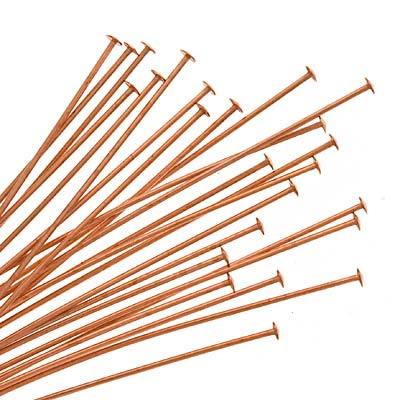
Anyhoos, to make a long story short, it turns out that the head part is just about the size of the solder pad on the bottom of your typical chinese perfboard which also just so happens to be the same width as your typical 1206 case resistor or capacitor. My plan is to strip the head pins of any coatings via chemical or abrasive means, grind them with the rotary tool giving the head a flat side ala waxing or waning moon shape, then whack them with a punch to flatten out the wire lead a little so it can grip the inside of the perfboard's through hole, pull them in place with some pliers to prevent them from rotating once in place, and then snip the leads flush with the perfboard's solder pad so that any trace wires can be laid flat on the pad and easily tacked into place.
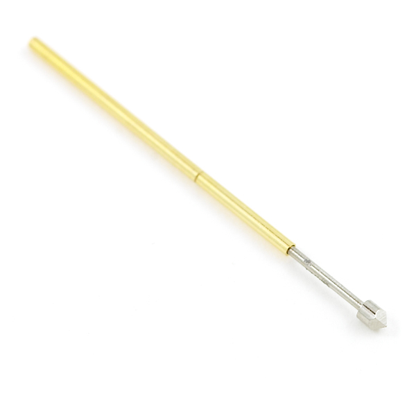
The only other problem is that man are those little SMT components slippery... soon as the solder on the pad liquifies they want to go all over the place! Furthermore best results I have obtained is by pre-tinning the solder pads and using dual irons with my previous generation of SMT adaper... the pins going to parallel port headers on junk motherboards. I will definitely need some sort of "holder downer"... I have an idea for one using the metal rod that a CD/DVD laser sled rides on fitted with a spring, some washers, and a couple "e clips"... something like a pogo stick tester used at sparkfun only a lot bigger. With something like what I am hoping to rig up it will apply constant down pressure on the component with the spring loaded tip while keeping it from rotating, and as soon as the joint liquifies on both sides, it will press the component flat on the pre-tinned pads.
Updates as soon as I get around to trying them out... I need to whip up a few linear voltage regulators, but I'm out of blank perfboard PCB's at the moment.
Anyhoos, to make a long story short, it turns out that the head part is just about the size of the solder pad on the bottom of your typical chinese perfboard which also just so happens to be the same width as your typical 1206 case resistor or capacitor. My plan is to strip the head pins of any coatings via chemical or abrasive means, grind them with the rotary tool giving the head a flat side ala waxing or waning moon shape, then whack them with a punch to flatten out the wire lead a little so it can grip the inside of the perfboard's through hole, pull them in place with some pliers to prevent them from rotating once in place, and then snip the leads flush with the perfboard's solder pad so that any trace wires can be laid flat on the pad and easily tacked into place.
The only other problem is that man are those little SMT components slippery... soon as the solder on the pad liquifies they want to go all over the place! Furthermore best results I have obtained is by pre-tinning the solder pads and using dual irons with my previous generation of SMT adaper... the pins going to parallel port headers on junk motherboards. I will definitely need some sort of "holder downer"... I have an idea for one using the metal rod that a CD/DVD laser sled rides on fitted with a spring, some washers, and a couple "e clips"... something like a pogo stick tester used at sparkfun only a lot bigger. With something like what I am hoping to rig up it will apply constant down pressure on the component with the spring loaded tip while keeping it from rotating, and as soon as the joint liquifies on both sides, it will press the component flat on the pre-tinned pads.
Updates as soon as I get around to trying them out... I need to whip up a few linear voltage regulators, but I'm out of blank perfboard PCB's at the moment.
Attached Files


Comment