![]() |
|
|
Thread Tools | Display Modes |
![]() |
#1 |
New Member
Join Date: Nov 2013
City & State: Tartu
My Country: Estonia
Line Voltage: 220V AC 50Hz
I'm a: Knowledge Seeker
Posts: 13
|
![]() Hello,
I hope this fits well into "weird devices" category. 
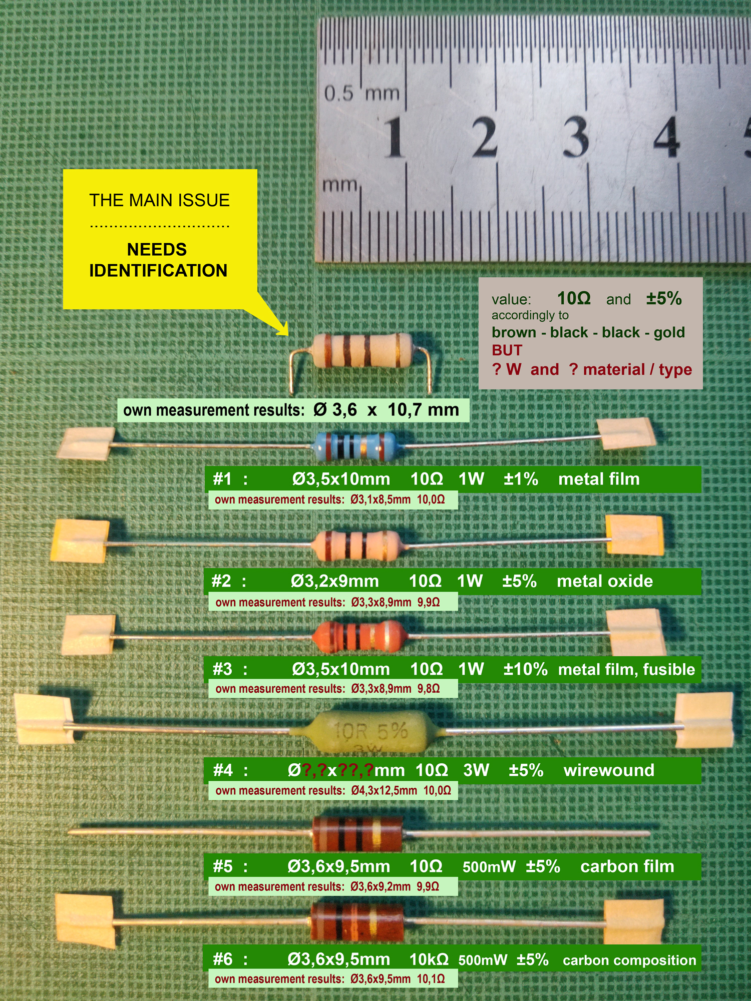
Please... anyone that knows better the science of resistors. Everything is on pictures. Stuff written in green boxes are official values accordingly the packages and datasheets. The rest is the rest. All I can add is that the subject`s background colour behind stripes is blueish light gray. As resistor #2 in the row is rather beige and physically smaller, I think it`s not right replacement for the main issue. As I didn`t had resistors #1 to #4 on hand reach at first place, I quickly learned hard way that 500mW or either carbon film type resistor is not a way to go there. I have a slight hunch that the subject might be 2W and metal oxide film due to similarities of this: https://projectpoint.in/index.php?route=product/product&product_id=501648635957 ... yet again some 3W variants look the same as well: https://www.amazon.com/uxcell-50pcs-.../dp/B07GMZDBNJ So I`m puzzled. IF 3W would be right way to go - could I use my #4 for replacement even though its wirewound type of resistor. Is there`s any significant difference between resistor materials type in this context? Secondly. 
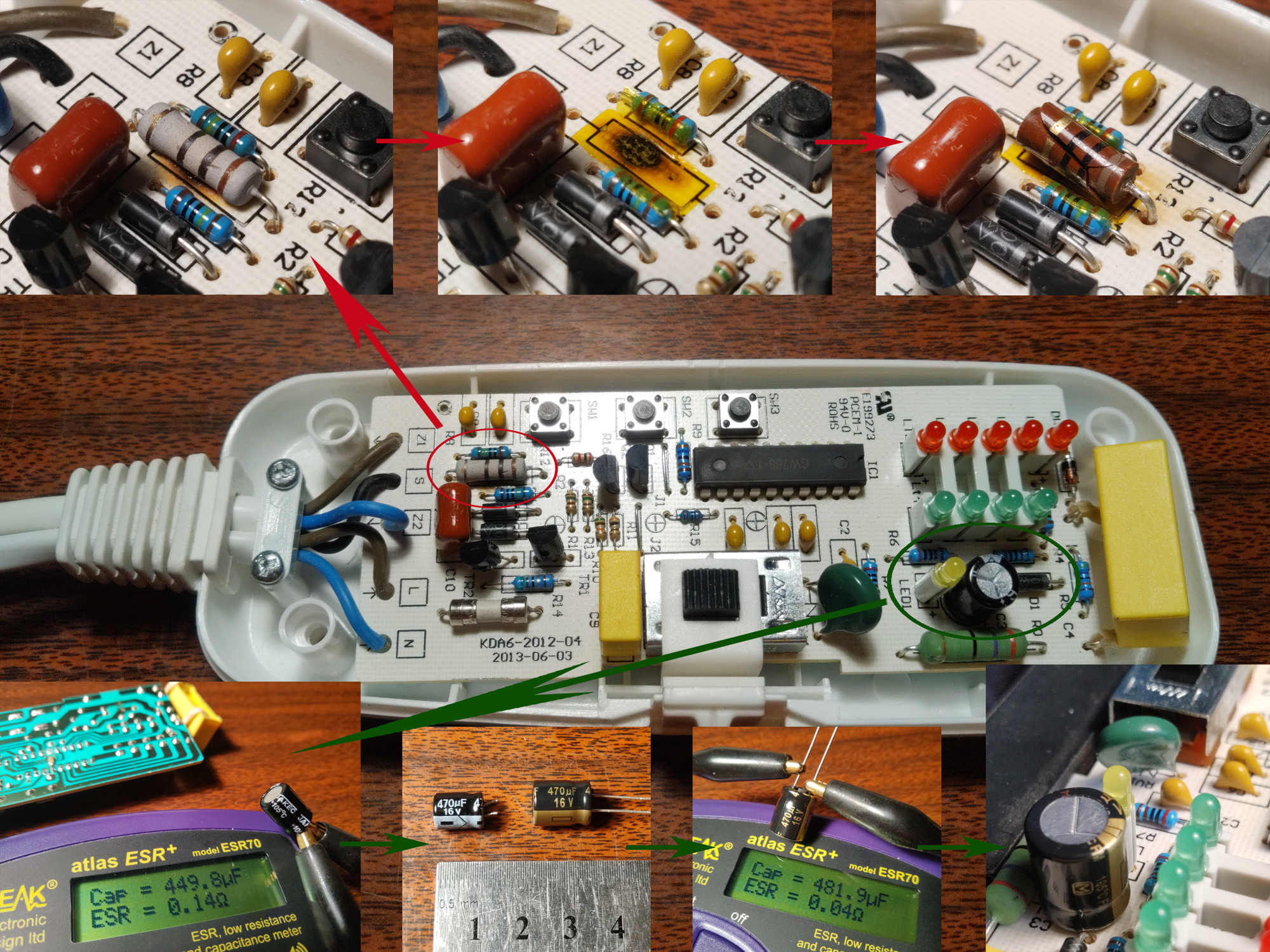
What would you do with the burn mark on PC board? Luckly the tracks are on the other side and not damaged. I applied some kapton tape on the spot before new resistor replacement. ..... Yes, the electrolytic capacitor is replaced as well. And atm I`m troubleshooting those yellow MPX X2 polypropylene capacitors as well, although it`s not shown on that second picture collage. Just to be sure of everything. Thanks in advance! Last edited by Sirgu; 02-13-2021 at 07:51 AM.. |
![]() |
![]() |
![]() |
#2 |
Badcaps Veteran
Join Date: Jun 2012
City & State: ☻
My Country: Canada
I'm a: Professional Tech
Posts: 6,979
|
![]() The resistor is likely a 1 watt, Some manufacturers resistors are smaller in size for the same wattage. Mount the resistor above the board so it is no longer touching and it will have better heat dissipation. Did you find the cause of the open resistor or was the original not open? The one you are asking about is likely a 1 watt metal film flame proof, I would use #1,2 or 3, You can use #4 if you have room,
Last edited by R_J; 02-13-2021 at 11:08 AM.. |
![]() |
![]() |
![]() |
#3 |
Great Sage 齊天大聖
Join Date: Dec 2009
City & State: Europe
My Country: some shithole run by Israeli agents
I'm a: Professional Tech
Posts: 24,386
|
![]() it's a 1w FLAME-PROOF resistor.
it's big because the oxide track is not continuous - it's a spiral so it can go open-circuit with minimal heat. that's also why it is dipped in gray cement instead of paint. |
![]() |
![]() |
![]() |
#4 |
Badcaps Veteran
Join Date: Dec 2010
City & State: Alberta
My Country: Canada
Posts: 1,993
|
![]() I think there is another bad part that cooks this resistor? Is it for a snubber or capacitive-power? Where is the triac I would check it.
There is a wide variance in the size of power resistors, a big game to make the smallest power resistor with the highest power rating. I compared dozens of different ones and realized it will drive you crazy. A resistor manufacturer will offer a "mini size" for the same power rating, but they operate much hotter. The larger the resistor is, the greater the heat dissipation. The better the materials (cement verses epoxy, wirewound verses film, copper leads verses FeCu) the hotter it can go. I don't think you can judge power resistors on size nowadays. |
![]() |
![]() |
![]() |
#5 |
New Member
Join Date: Nov 2013
City & State: Tartu
My Country: Estonia
Line Voltage: 220V AC 50Hz
I'm a: Knowledge Seeker
Posts: 13
|
![]() Thanks everyone! It broadens my knowledge a lot.
R_J - Yes, this original main issue resistor is open. And the burn mark is seemingly a long-term result. Not a sudden cause of resistor failure. And there`s plenty of space to solder any of them there. stj - #2, #3 and #4 also have this kind of hard matt coating while #1 is glossy paint (or epoxy for that matter). I never knew the considerations for materials used for finishing. Likewise I don`t know much of a difference of resistor type technologies. redwire - Oh my, thanks for the input! There`s so much to discover. Snubber vs capacitive-power - How can I find out? So... putting this all together my #2 seems almost like a replacement but probably it will heat up faster and will eventually fail later. I am assuming that: 1.) Wattage value can be exact OR bigger (if it physically fits) but never smaller than original. 2.) Whereas `flame proof` type is a must accordingly the context. 3.) Plus physical size should be at least the same up to its values for better cooling. [Correct me if I am wrong in any aspects.] ..... As follow-up question: -This polypropylene capacitor needs to be replaced, right? As it`s capacitance (exactly -20% of 1.0µF) is lower than stated capacitance tolerance (±10%). Also resistance slightly out of range. |
![]() |
![]() |
![]() |
#6 | |
New Member
Join Date: Nov 2013
City & State: Tartu
My Country: Estonia
Line Voltage: 220V AC 50Hz
I'm a: Knowledge Seeker
Posts: 13
|
![]() Quote:
Two of them read: MAC 97A6 13H One is: 13001 98T And the last one: A1015 GR011 Make and model of thing itself (if it helps anyhow): Rubicson KDA6-FT electric blanket [some pictures here] Controller looks as following: https://www.youtube.com/watch?v=5K5p7bOWtNo&ab_channel=Per-GunnarH.%C3%85gren Someone has done curious teardown whereas those triacs and the rest is pretty clearly seen as well. The misbehaviour of controller LED`s in the video are the same as my unit (stating that smth is wrong) but seemingly his big grey resistor next to "S" marking on top of black wire is not burnt and the stripes colour code is totally smth else than mine. |
|
![]() |
![]() |
![]() |
#7 |
Great Sage 齊天大聖
Join Date: Dec 2009
City & State: Europe
My Country: some shithole run by Israeli agents
I'm a: Professional Tech
Posts: 24,386
|
![]() some data
|
![]() |
![]() |
![]() |
#8 |
Badcaps Veteran
Join Date: Jun 2012
City & State: ☻
My Country: Canada
I'm a: Professional Tech
Posts: 6,979
|
![]() Here is the MAC97A6
|
![]() |
![]() |
![]() |
#9 |
Great Sage 齊天大聖
Join Date: Dec 2009
City & State: Europe
My Country: some shithole run by Israeli agents
I'm a: Professional Tech
Posts: 24,386
|
![]() where does that microcontroller get 5v??
a zener diode?? |
![]() |
![]() |
![]() |
#10 | |
Badcaps Veteran
Join Date: Jul 2011
City & State: Sunny Jacksonville FL
My Country: USA
Line Voltage: 120 Volts 60 HZ
I'm a: Knowledge Seeker
Posts: 2,601
|
![]() Quote:
I would also recommend when you put the new resistor on the board do not mount it flush to the board leave a space between the board and the resistor so does not keep burning the board
__________________
9 PC LCD Monitor 6 LCD Flat Screen TV 30 Desk Top Switching Power Supply 10 Battery Charger Switching Power Supply for Power Tool 6 18v Lithium Battery Power Boards for Tool Battery Packs 1 XBox 360 Switching Power Supply and M Board 25 Servo Drives 220/460 3 Phase 6 De-soldering Station Switching Power Supply 1 Power Supply 1 Dell Mother Board 15 Computer Power Supply 1 HP Printer Supply & Control Board * lighting finished it * These two repairs where found with a ESR meter...> Temp at 50*F then at 90*F the ESR reading more than 10% 1 Over Head Crane Current Sensing Board ( VFD Failure Five Years Later ) 2 Hem Saw Computer Stack Board All of these had ![]() All of the mosfet that are taken out by bad caps ![]() |
|
![]() |
![]() |
![]() |
#11 |
Badcaps Veteran
Join Date: Feb 2010
City & State: S.F. Bay area
My Country: USA
Line Voltage: 120V 60Hz
I'm a: Knowledge Seeker
Posts: 39,116
|
![]() Can you attach good clear high res straight shots of the whole top and bottom side of the board?
__________________
Never stop learning Basic LCD TV and Monitor troubleshooting guides. http://www.badcaps.net/forum/showthr...956#post305956 Voltage Regulator (LDO) testing: http://www.badcaps.net/forum/showthr...999#post300999 Inverter testing using old CFL: http://www.badcaps.net/forum/showthr...er+testing+cfl Tear down pictures : Hit the ">" Show Albums and stories" on the left side http://s807.photobucket.com/user/budm/library/ TV Factory reset codes listing: http://www.badcaps.net/forum/showthread.php?t=24809 |
![]() |
![]() |
![]() |
#12 |
New Member
Join Date: Nov 2013
City & State: Tartu
My Country: Estonia
Line Voltage: 220V AC 50Hz
I'm a: Knowledge Seeker
Posts: 13
|
![]() |
![]() |
![]() |
![]() |
#13 |
New Member
Join Date: Nov 2013
City & State: Tartu
My Country: Estonia
Line Voltage: 220V AC 50Hz
I'm a: Knowledge Seeker
Posts: 13
|
![]() This little fellow?
|
![]() |
![]() |
![]() |
#14 |
Badcaps Veteran
Join Date: Jun 2012
City & State: ☻
My Country: Canada
I'm a: Professional Tech
Posts: 6,979
|
![]() I suspect there is a problem with the blanket or wiring to the blanket that caused the controller to fail. If the led's are flashing the same way as the video, it indicates there is no blanket connected, no load and no feedback/temp control. The ic is likely a PIC microcontroller
Last edited by R_J; 02-15-2021 at 05:22 PM.. |
![]() |
![]() |
![]() |
#15 |
Badcaps Veteran
Join Date: Jul 2011
City & State: Sunny Jacksonville FL
My Country: USA
Line Voltage: 120 Volts 60 HZ
I'm a: Knowledge Seeker
Posts: 2,601
|
![]() I wonder if you could not test the blanket controller by using a 100 watt incandescent light bulb but you would probably need to light bulbs the terminal marked “S” that this might either common or temperature sensor but unless you reverse engineer it you would not know for sure
Last edited by sam_sam_sam; 02-15-2021 at 05:21 PM.. |
![]() |
![]() |
![]() |
#16 | |
New Member
Join Date: Nov 2013
City & State: Tartu
My Country: Estonia
Line Voltage: 220V AC 50Hz
I'm a: Knowledge Seeker
Posts: 13
|
![]() Quote:
-Yes, undoubtly I cannot be sure at this point that balnket is totally okay. All I know that its wiring is continuous circuit without any drawbacks while moving, bending blanket anyhow. But still suspicious about its wiring resistance change over time when material temperature rises or drops. -On the other hand - No! Those LEDs flasing like that are not indicating the absence of blanket. I remember when the controller was still in working condition you could set the power and timer even though when blanket was not connected in socket with it. So I assume the turbulence of LEDs is a sign of ANY kind of issue on component basis - the situation were customary end-user should stop searching the cause of wrong use and trash the unit to avoid further dangers. Unfortunately I`m not the one. ![]() Last edited by Sirgu; 02-16-2021 at 03:22 PM.. |
|
![]() |
![]() |
![]() |
#17 |
New Member
Join Date: Nov 2013
City & State: Tartu
My Country: Estonia
Line Voltage: 220V AC 50Hz
I'm a: Knowledge Seeker
Posts: 13
|
![]() Some notes:
The printings on PCB in video read E199273 PCEM-1 94V-O ROHS which are the same as mine, then on the other edge KDA6-2015 wheras mine reads KDA6-2012-04 2013-06-03 Then pause video at 5:20 and the colour code for the "S" big resistor seems like red-red-gold-silver = 2.2Ω ±10% ? (The rest set of big components look the same as far as eye can tell.) Could it funnily be like few years later they found out that 2.2Ω ±10% is suitable there instead of 10Ω ±5% ?? |
![]() |
![]() |
![]() |
Thread Tools | |
Display Modes | |
|
|