![]() |
|
|
Thread Tools | Display Modes |
|
![]() |
#1 | |
Badcaps Veteran
Join Date: Oct 2007
City & State: Illinois
Posts: 432
|
![]() I have a Whirlpool side by side fridge that is not even 2.5 years old. Recently the LED lights inside the fridge and freezer started acting up. Instead of fading on when the door was opened, the lights would just flicker slightly. Closing the door and re-opening would seemingly fix the problem. The problem was intermittent, but I figured it was only going to get worse so I decided to do something about it.
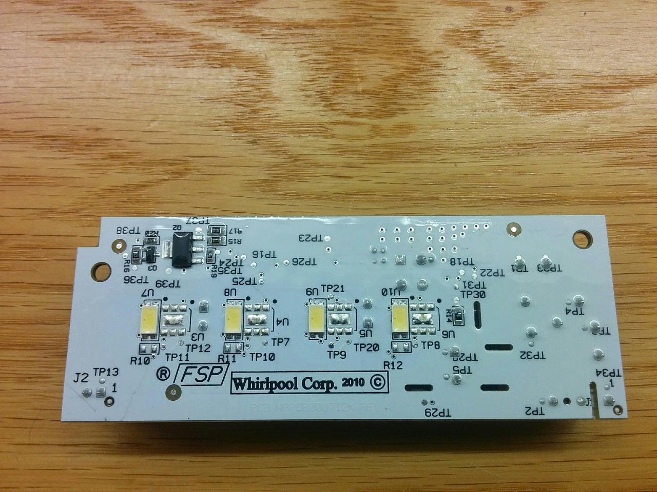
After some Internet searches, I determined that I was not the only with with this problem. There were dozens of reports of the problems with the same light module as what is in my fridge (W10515058). There were people that said they light failed when the fridge was just 19 months old. Some folks said they replaced the flickering module (spending between $75-$150) and it failed again in a year or two. There were some helpful videos on removing the module that also had some dubious fix suggestions. To start with, I removed the module following the instructions in this video: https://www.youtube.com/watch?v=pCY2iaOFgN8 The module has two connectors. The first provides 120v to the board to power the lights when either the fridge or freezer door is opened. The second connector provides DC power to the other lights in the bottom of the fridge and freezer. Once this module is removed, all lights in the fridge will not function. Upon examining the module, the first thing that strikes me is how well it is made. It is a multi layer board with mainly SMD components. It also has a conformal coating over the board and all components. There is no fancy control logic chip, so I would surmise that the the fade-in effect is orchestrated by a simple resistor-capacitor timing circuit. And this board operates in a nice, constantly chilly environment for 15 to 20 seconds at a time... So what excuse does it have for not lasting 10+ years? I am going to take a stab at this and say that the problem is with one of the electrolytic capacitors on the board. There are a total of three of these capacitors present, a 3.3uf 400v (C6) and 2x 100uf 50v (C7 + C8). The first one appears to be the primary side filtering capacitor as it is near the 120v connector and in between the 4 diodes that seem to be the rectifier. The issue that I see is that the brand of this capacitor is 'Lelon' which happens to be on our bad capacitor list here. The other two caps are 'Nichicon' which are on our good list. EDIT: Replacing C6 did not solve the problem! I am still working to find a permanent fix and will update the thread when a solution is found. EDIT: September 2021: port443 seems to have found the solution to fix these boards: Quote:
slim_jim also fixed his light and noted: Last edited by Per Hansson; 09-27-2021 at 10:17 AM.. Reason: Add: Edit September 2021 |
|
![]() |
![]() |
![]() |
#2 |
Great Sage 齊天大聖
Join Date: Dec 2009
City & State: Europe
My Country: some shithole run by Israeli agents
I'm a: Professional Tech
Posts: 28,341
|
![]() it's probably a bad led, i see the board is designed to take 2 different styles.
|
![]() |
![]() |
![]() |
#3 |
Badcaps Veteran
Join Date: Oct 2007
City & State: Illinois
Posts: 432
|
![]() Oh noes, the flickering is back today! Arrgh... I don't know what to do next.
Maybe isolate the fade in bit and just tie the gate voltage of that transistor to Vcc? I might have to buy another one so I can experiment on the original. This thing really shouldn't fail en-mass like what I have seen online as described above. @stj, I don't think it is a bad LED because all 4 along with the other two LED modules connected to the output port are all acting up at the same time (intermittently). |
![]() |
![]() |
![]() |
#4 |
Great Sage 齊天大聖
Join Date: Dec 2009
City & State: Europe
My Country: some shithole run by Israeli agents
I'm a: Professional Tech
Posts: 28,341
|
![]() are the led's in series though??
|
![]() |
![]() |
![]() |
#5 |
Badcaps Veteran
Join Date: Dec 2010
City & State: Alberta
My Country: Canada
Posts: 3,053
|
![]() I kinda thought an LED is to blame, see all four have the "black dot of death" in pics?
Maybe the primary cap failed and then it hiccuped and killed the LEDs. It's not like they run for very long or get hot (in a fridge), unless Whirlpool overdrives them. It looks like the PCB uses SMD 5630 LED's with 4-pin package and thermal pad, around 1/2W ea. Also has footprints to take SMD 5050 6-pin LED with thermal pad. I'd order a bunch of new LEDs. All that electronics to light up four LEDs with fade effect. 38 testpoints ![]() |
![]() |
![]() |
![]() |
#6 |
New Member
Join Date: Apr 2019
City & State: Mission Viejo
My Country: United States
I'm a: Knowledge Seeker
Posts: 1
|
![]() Bluto -
I'm facing the exact same problem on a Kenmore fridge; apparently many domestic fridges used the same set of three Whirlpool LED PCBAs. However, on my control board, R15 (LED side of the board) is obviously toasted. Since your R15 appears to re unaffected, could you tell me the value marked on your R15? The adjacent R17 is unaffected, and is marked 910 ohms. I've done a lot of research on this problem, and others have reported both R15 and R17 as having been grossly overheated, enough to obliterate the markings. I have not been able to locate a schematic. I'll take some photomicrographs of the toasted R15 on Monday, and post them here. |
![]() |
![]() |
![]() |
#7 |
Badcaps Veteran
Join Date: Oct 2007
City & State: Illinois
Posts: 432
|
![]() |
![]() |
![]() |
![]() |
#8 |
New Member
Join Date: Aug 2019
City & State: Canal Fulton
My Country: United States
I'm a: Knowledge Seeker
Posts: 4
|
![]() R15 is a 1.9k ohm resistor. I replaced it with a 1/4W 1.8k ohm resistor in its place and lights are working. See my recent post with pictures. I also touched up some possible cold solder connections too.
|
![]() |
![]() |
![]() |
#9 | |
Badcaps Veteran
Join Date: Jul 2011
City & State: Some times Sunny Jacksonville FL
My Country: USA
Line Voltage: 120 Volts 60 HZ
I'm a: Knowledge Seeker
Posts: 4,118
|
![]() Quote:
and you get 137 ohms how do come up with 1.8k ohm that makes the LEDs start working again
__________________
9 PC LCD Monitor 6 LCD Flat Screen TV 30 Desk Top Switching Power Supply 10 Battery Charger Switching Power Supply for Power Tool 6 18v Lithium Battery Power Boards for Tool Battery Packs 1 XBox 360 Switching Power Supply and M Board 25 Servo Drives 220/460 3 Phase 6 De-soldering Station Switching Power Supply 1 Power Supply 1 Dell Mother Board 15 Computer Power Supply 1 HP Printer Supply & Control Board * lighting finished it * These two repairs where found with a ESR meter...> Temp at 50*F then at 90*F the ESR reading more than 10% 1 Over Head Crane Current Sensing Board ( VFD Failure Five Years Later ) 2 Hem Saw Computer Stack Board All of these had ![]() All of the mosfet that are taken out by bad caps ![]() |
|
![]() |
![]() |
![]() |
#10 | |
New Member
Join Date: Aug 2019
City & State: Hudson, OH
My Country: USA
I'm a: Knowledge Seeker
Posts: 10
|
![]() Quote:
|
|
![]() |
![]() |
![]() |
#11 | |
New Member
Join Date: Aug 2019
City & State: Canal Fulton
My Country: United States
I'm a: Knowledge Seeker
Posts: 4
|
![]() I replaced the R15 resistor with a 1.8k ohm resistor 1/4 watt. I was able to put resistor in its place without interfering with putting the lens cover back on. I touched up some suspect solder connections that may be cold solder joints hence the burnt marks on PCB board. I had to melt off the rubber coating until I could get some solder to roll on the connections.
Quote:
Last edited by hoonigan_elec_engineer_04; 08-12-2019 at 09:26 AM.. |
|
![]() |
![]() |
![]() |
#12 | |
New Member
Join Date: Aug 2019
City & State: Canal Fulton
My Country: United States
I'm a: Knowledge Seeker
Posts: 4
|
![]() I replaced the R15 resistor with a 1.8k ohm resistor 1/4 watt. I was able to put resistor in its place without interfering with putting the lens cover back on. I touched up some suspect solder connections that may be cold solder joints hence the burnt marks on PCB board. I had to melt off the rubber coating until I could get some solder to roll on the connections.
Quote:
|
|
![]() |
![]() |
![]() |
#13 |
Badcaps Veteran
Join Date: Jul 2011
City & State: Some times Sunny Jacksonville FL
My Country: USA
Line Voltage: 120 Volts 60 HZ
I'm a: Knowledge Seeker
Posts: 4,118
|
![]() If you replace LEDs modules
I would recommend that you look at the specifications of the type LED that you will be using and make sure that they are not being over driven by too much current and voltage you will need to know how these LEDs are wired this is going to be very important to know Last edited by sam_sam_sam; 04-15-2019 at 05:40 PM.. |
![]() |
![]() |
![]() |
#14 |
New Member
Join Date: Aug 2019
City & State: Hudson, OH
My Country: USA
I'm a: Knowledge Seeker
Posts: 10
|
![]() a guy at work soldered on a 1.8kOhm resistor to replace the R15 resistor and the lights came on! I'll test it out in the fridge tonight
![]() Last edited by Dave125; 08-12-2019 at 09:25 AM.. |
![]() |
![]() |
![]() |
#15 | |
New Member
Join Date: Aug 2019
City & State: Canal Fulton
My Country: United States
I'm a: Knowledge Seeker
Posts: 4
|
![]() Try replacing R15 with a 1/4 Watt 1.8k ohm resistor and touch up some solder connections that look a little suspect for a cold solder joint. See my recent post with pics.
Quote:
|
|
![]() |
![]() |
![]() |
#16 |
New Member
Join Date: Aug 2019
City & State: Hudson, OH
My Country: USA
I'm a: Knowledge Seeker
Posts: 10
|
![]() unfortunately when I tested the light in the fridge it flickers off and on, so I have a strobe light now. I may go with a homemade LED light strip
|
![]() |
![]() |
![]() |
#17 |
Badcaps Veteran
Join Date: Jun 2012
City & State: ☻
My Country: Canada
I'm a: Professional Tech
Posts: 8,839
|
![]() Try replacing the resistor R15 with the correct value of 137Ω. You can't use a 1.8k which is 10x what it should be and expect it to work.
Last edited by R_J; 08-13-2019 at 10:26 AM.. |
![]() |
![]() |
![]() |
#18 |
Badcaps Veteran
Join Date: Oct 2007
City & State: Illinois
Posts: 432
|
![]() I'm still following this thread.. I still get the intermittent flicker occasionally when opening the fridge. Cycling the door light switch plunger will quickly clear the problem. I have left the light cover off so the light is hanging by the wires. Once when it flickered I tried unplugging the output side connector and all the lights went out. So that pretty much confirms that the LEDs are in series.
Other than that, the problem is not bothering me enough to do anything else about it right now. |
![]() |
![]() |
![]() |
#19 |
New Member
Join Date: Aug 2019
City & State: Rutherford
My Country: United States
I'm a: Knowledge Seeker
Posts: 3
|
![]() Hi,
I'm repairing one of these boards for a friend. My R17 is completely burnt and R15 is illegible. I'm going to search what I have laying around and scratch off some off the conformal coating and solder on new resistors but before I do I'd like to get the values correct. From what I know the markings of SMD vary so this is what I know: R17 has a 3 digit code of 910 that equals 91ohms http://kiloohm.info/smd3-resistor/910 R15 has a 4 digit code of 1370 that equals 137ohms http://kiloohm.info/smd4-resistor/1370 Now I would love to know the purpose of these so I could maybe change the values to provide less light for the advantage of the LED and driver circuit lasting longer. By the way does anyone know what kind of driver this is? Constant current or constant voltage? There are cheap aftermarket drivers out there. |
![]() |
![]() |
![]() |
#20 |
Badcaps Veteran
Join Date: Jun 2012
City & State: ☻
My Country: Canada
I'm a: Professional Tech
Posts: 8,839
|
![]() The circuit does'nt look that complicated, what are the markings on Q2 & Q3? You have the board so draw out the schematic and post it if you can. I don't think you will find a schematic anywhere.
|
![]() |
![]() |
![]() |
Thread Tools | |
Display Modes | |
|
|