![]() |
|
|
Thread Tools | Display Modes |
|
![]() |
#1 | ||
master hoarder
Join Date: May 2008
City & State: VA (NoVA)
My Country: U.S.A.
Line Voltage: 120 VAC, 60 Hz
I'm a: Hobbyist Tech
Posts: 10,860
|
![]() Okay, before I begin, let me note here that I am no expert on the matter. All of the info below is based on information that I found on the web, in capacitor datasheets, and some experiments I conducted myself.
So what is electrolytic capacitor reconditioning (also known as reforming)? Basically, it is applying the maximum rated voltage on capacitor for a period of time. This is done in order to rejuvenate the electrolyte and/or aluminum oxide layer inside the capacitor. Which electrolytic capacitors should be reformed? - Ones that have been sitting in storage for a long time (regardless of whether they are new or used) - Used capacitors that came from a circuit, where the operating voltage was much lower than the rated voltage of the capacitor. Example: 6.3V electrolytic caps that were used on the CPU filter output of a motherboard (where the working voltage is often less than 1/3 to 1/4 of the rated voltage.) Why should electrolytic capacitors be reformed? According to Panasonic (information found in HFQ series datasheet): Quote:
![]() How to reform electrolytic capacitors: More from the same Panasonic datasheet: Quote:
Now, reforming only one capacitor at a time is slow. Therefore, building a “cap reformer” to recondition multiple caps at a time should definitely speed things up. And this is pretty much the goal of this thread – to show some simple working examples to build your own. There are more than a few ways to do this. In general, all you will need is a handful of resistors and something to let you connect and disconnect the electrolytic caps easily from the cap reformer circuit. I used a breadboard for this. And here is what my cap reformer looked like: 
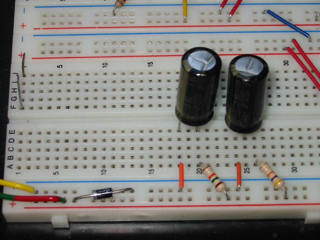
(Note: I only have two caps in the above picture, but later I expanded my circuit to do up to 11 caps at a time.) You could also use a ZIF IC socket in place of the breadboard (thanks to Per Hansson for suggesting this idea to me). It will be both cheaper and easier to reform caps with short leads or leads that have excess solder (with a breadboard, the leads must be long enough to go down in the contacts and be clean enough to fit in the breadboard holes) So for the ZIF socket, something like this should do: http://www.ebay.com/itm/2PCS-NEW-Hot...cAAOxyjxlTKpxV Then, just wire your cap reformer circuit. Schematic below if you're not quite sure what to do here: 
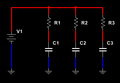
In the circuit above, capacitors C1, C2, and C3 are the electrolytic capacitors that are to be reformed, while resistors R1, R2, and R3 are the series current-limiting resistors for each cap respectively. Of course, you can size your cap reformer to do as many caps at a time as you want. Just add a series resistor for every cap you add (i.e. continue the pattern to the right with the above circuit). As per the Panasonic datasheet again, the series resistors can all be 1 KOhm. However, according to some tests I did, it may be better to use higher resistances if the caps to be reformed are very old (as in, 10+ years in storage) or if they were used with a much lower voltage than their rated voltage (again, motherboard CPU caps should come to mind here), otherwise they may develop and internal short-circuit. For my reformer, I used mostly 10 KOhm resistors (but also tried a few 15 KOhm and 47 KOhm ones). Just about anything between 1 KOhms and 100 KOhms will work, since this is nowhere near exact science. From my experiments, however, the further you go above 10 KOhms, the longer it takes for the caps to charge (especially for ones over 1000 uF), and this will slow down the reform process or won't reform the capacitors to the maximum voltage you selected with the source. With that being said, if you find that some of your caps have not reached 90% of the source voltage after 30 minutes of reforming, then one of the following could be happening: (1) The series resistor has too large of a resistance for the capacitor it is reforming (2) The cap is possibly excessively leaky (3) A combination of the two above The best solution for this would be to lower the resistance of the series resistor. However, do NOT use less than 1 KOhms (except possibly for very large caps, like 400V, 500 uF… or 25V, 4700 uF). If the cap still does not reach 90% of the source voltage after this, you should test the cap's leakage current and compare to datasheet maximum (see Leakage Current thread). And if the cap shows only a few mV to 1V across its terminals after a minute or so of reforming – STOP! The capacitor has likely become short-circuited internally. Depending on your multimeter, you *may* be able to verify this by measuring the resistance. But don't count on it. I had a few caps short-circuit, and while some read as low as just several Ohms, one read 1.8 KOhms (which is far from a short-circuit… but if you put this cap in a device and apply power, it will likely short almost immediately. Some of mine did when I used a lower series resistor.) To be continued... (10000 characters limit) ![]() Last edited by momaka; 11-22-2015 at 10:35 PM.. |
||
![]() |
![]() |
![]() |
#2 | |
master hoarder
Join Date: May 2008
City & State: VA (NoVA)
My Country: U.S.A.
Line Voltage: 120 VAC, 60 Hz
I'm a: Hobbyist Tech
Posts: 10,860
|
![]() Part 2... continued from above.
Anyways, the last part in the above schematic is the source, V1. It should provide a voltage as close as possible to the capacitors' rated voltage (but not higher than that.) Because of the series resistors, the caps won't draw much current, even when they are fully discharged. So a few milliamperes (mA) should be more than enough in most cases. If you are using a standard power adapter, you need not worry about the current, as even the smallest adapters are usually capable of at least 100 mA. Which brings me to my next point: what to use as the source. If you tend to hoard junk like me, you probably have a stash of spare power adapters rated for various voltages. For reforming 6.3 V, 10 V, and 16 V caps, for example, I used power adapters rated for 5 V, 9 V, and 15 V respectively – not ideal, but still fairly close to what the caps are rated for. Of course, keep in mind that the output voltage of many adapters varies with the load. On that note, be especially careful with linear adapters, because they output a much higher voltage when unloaded (for example, I have a linear power adapter also rated for 9 V DC, but it actually outputs 16.5V when unloaded). This matters, because the capacitors (that are to be reformed) won't draw much current once they charge up. So the power adapter may supply higher voltage that what is called for. Therefore, always measure the actual unloaded output voltage of the power adapter before using it. An alternative to using many different power adapters is to use a single laptop power adapter and build some kind of circuit to regulate the voltage output (but keep in mind that most laptop adapters output 16 to 20 Volts, so reforming will be possible for only 6.3 V, 10 V, 16 V, and maybe 25V caps.) The simplest way to scale down the output voltage of the laptop adapter is do build a voltage divider circuit with a few resistors. The three voltage divider circuits below show how to get 6.23 V, 9.75 V, and 15.35 V with some common resistor values from a 19.5 V adapter. Simply hook the output of these voltage dividers in place of V1 in the first diagram. Note: the 1 KOhm resistors used in the above diagrams should be rated for at least ¼ Watts and preferably ½ Watts if you don't want them to run too hot. Another thing to mention: if you feel that the above voltages are too close to the capacitors' maximums, you can always add a loading resistor across the voltage divider's output to lower the voltage. The circuit schematic below shows this: Here, the loading resistor is R_load and it is chosen as 10 KOhms. With this resistor, the output voltage of the above voltage dividers will drop to 6.04 V, 9.28 V, and 15.03 V respectively. However, it is very likely that you won't need to do this, because the current draw by the caps (due to their leakage current) should already make those output voltages above to drop lower. Also, the series resistors should prevent damage to the caps, even if the voltage does go slightly above their maximum rated. On that note, it should be mentioned that many electrolytic capacitors can withstand (for a short period of time) a surge voltage up to 20% higher than their rated maximum voltage. Therefore, if you run a 6.3 V-rated cap at, say, 6.4 Volts, it is unlikely that it will pop. And finally, if you want to avoid playing around with voltage dividers and different power adapters, you can always just use a potentiometer in place of the two resistors in the voltage divider circuit. This would allow the voltage to be adjusted anywhere between 0 and your adapter's maximum voltage. However, the only thing I will mention here is to pay attention to the potentiometer's power handling capacity. If you want to use a 1 KOhm potentiometer with a 19.5 Volt laptop adapter, then the potentiometer should be rated to handle at least ½ Watt. Note that this will be a rather big pot. If you use a 2 KOhm pot or higher resistance, then that rating can be ¼ Watts. And for 4.7 KOhms and above, 1/8 Watt will do. But as you go higher in the potentiometer resistance, this will also decrease the current that will get to your cap reformer circuit. So you shouldn't really go too high or too low on the potentiometer resistance. 2.2 to 4.7 KOhms is probably a good middle ground. For how long can I store my reformed capacitors? I can't say for sure. It likely varies for different capacitor brands and series. Many datasheets will specify a Shelf Life where the capacitor is guaranteed to meet specs after X number of hours in storage at Y °C. This is typically 500, 1000, and 2000 hours at 85 or 105 °C. (However, a few datasheets note this to be true only after capacitor "pre-treatment" [i.e. reforming] to the full DC working voltage for 30 minutes.) The above statement then probably brings the question: what about storing capacitors at a lower temperature and will that help? - That, unfortunately, is another item that is not specifically mentioned in any datasheet I have seen so far. Therefore, I cannot answer. Panasonic does state the following, though: Quote:
I don't know, but this does seems to make sense to me. A few years back, I was able to borrow an ESR meter (ESR Micro v4) from a friend, and I tested caps in my “good” stash. Many were at least a few years old, but they all tested okay for both ESR and capacitance. So I think there is some merit to my assumptions above. Moreover, when I was experimenting with the cap reformer, I noticed that I was able to “restore” back some caps that wouldn't want to hold a voltage higher than the circuit I pulled them from (notably some CPU caps that had 1.5 Volts across them their entire life in circuit). After reforming, now I can charge them to any voltage and they will stay there for a good few days before discharging. So I think the bottom line is: it is okay to keep caps in storage for a year or two. But if you want to make sure that the caps' specs don't deteriorate at all from the factory, then consider reforming them every year or two (again, that depends on what the datasheet for your caps recommends.) That is all from me (really, only a tiny four and half pages in MS Word ![]() Last edited by momaka; 11-22-2015 at 10:23 PM.. |
|
![]() |
![]() |
![]() |
#3 |
Badcaps Veteran
Join Date: Apr 2005
Posts: 1,560
|
![]() Great write-up and cool stuff - the idea of using a laptop 19.5V supply as a single supply for a number of different voltages is clever and practical. You may also want to recap the adapter with good caps if possible.
|
![]() |
![]() |
![]() |
#4 |
Badcaps Veteran
Join Date: Dec 2008
Posts: 5,352
|
![]() momaka -
Thank you very much. I have to go and pay my credit card bill now, but when I come back I intend to read this in depth and start ordering parts to construct the jig. ![]()
__________________
"...I suppose he wants to be free of youthful associations, as most of us do." -Robertson Davies "...don't say oh my god, your god is far away from you. I give you massage. I am your god now." -Luo Dong |
![]() |
![]() |
![]() |
#5 |
Badcaps Veteran
Join Date: Dec 2008
Posts: 5,352
|
![]() So I measured my variable wall-wart:
Here are the unloaded voltages I got: 1.5V setting - 3.3V 3V setting - 5.11V 4.5V setting - 7.25V 6V setting - 9.28V 7.5V setting - 11.47V 9V setting - 13.70V 12V setting - 18V I'm going the 1/2 watt potentiometer route for now. In the future I hope to build something more permanent with voltage dividers specifically for my wall-wart (ideally I'd like to run a macro in LTSpice which calculates voltages based on different resistor values, but I can't find a way to introduce an AC voltage source into the program). Here's my shopping list so far, am I missing anything? It occurs to me that the wall-wart isn't that great of an idea, and I'd be better off using a laptop adapter. I've got one that does 24V, so it would be good for 25V caps, and I'd be able to do more than 10 at a time - at most with the wall-wart which only has a max of 300mA. Now assuming I've got two of those ZIF sockets with 14 caps on each, that's 28 caps drawing let's say an average of 30mA each, still less than an amp. Would the 1/2 watt pot be sufficient for this kind of load? |
![]() |
![]() |
![]() |
#6 | |||||||
master hoarder
Join Date: May 2008
City & State: VA (NoVA)
My Country: U.S.A.
Line Voltage: 120 VAC, 60 Hz
I'm a: Hobbyist Tech
Posts: 10,860
|
![]() If you get a 1 KOhm pot and are planning to that 24 V power adapter, then the pot should be rated for 1 Watts. Calculations:
power draw P = (V^2)/R = (24^2)/1000 = 24 • 24 / 1000 = 0.576 Watts An alternative would be to use a 1.5 KOhm (or higher) 1/2 W potentiometer. Quote:
V_out = V_in • (R2 /(R1 + R2)) where V_in is the input voltage of the power adapter (same as source V1 above), R1 and R2 are the voltage divider resistors, and V_out is the output voltage you get. There are millions of combinations of resistors you can use to get a certain voltage. However, just watch out so that you don't overpower any of the resistors (i.e. force more than 1/2 W through a 1/4W resistor, or something like that). In general, if you are using an adapter of 18 V or above, then try to keep the sum of the resistance of R1 and R2 above in the 1-10 KOhm range. Quote:
Looks fine. Are you wire wrapping everything, by the way? Quote:
http://www.badcaps.net/forum/showthr...499#post609499 That said, a *fully discharged* capacitor will draw a *peak current* that is limited by the current-limiting series resistor. Example: 25 V cap that is to be reformed with a 1 KOhm current-limiting series resistor and 24 V power adapter. Peak current draw: I_peak = adapter voltage / series resistor resistance I_peak = 24 / 1000 = 24 mA If you are reforming 10 caps at a time with the same as the above configuration, the power draw will be 24 • 10 = 240 mA. *However*, as the caps charge up, the voltage across them will rise. The current draw for each cap after the initial I-peak current will then be: I = adapter voltage - voltage across cap / series resistor resistance Let's assume the voltage across the caps has gone up to 10V after a few moments. Then: I = 24 - 10 / 1000 = 14 / 1000 = 14 mA Depends on what you have as the series resistor resistance. The pot will likely burn out if you use 1 KOhm series resistors and do several caps at a time. If you use 10 KOhm series resistors, however, the pot might be able to handle up to 10 caps at a time. Note that I haven't done any "hard" calculations on this, though. But a 1/2 Watt pot will not be able to handle as much power as two separate 1/2 Watt resistors in a voltage divider. Quote:
I already shorted out a handful before I started experimenting with the cap reformer, so this is definitely something useful to have IMO. I am actually planning to eventually reform all of my caps I have in stock in stock. Quote:
This is why sometimes electrolytic caps are also referred to as "self-healing", meaning that their specs can be brought back simply by applying power to them. Quote:
![]() Indeed. Generally, that's how I would do it too, but I only mentioned the simple resistor voltage dividers above to keep costs and complexity to a minimum so that even people with little electronics knowledge can build this. Quote:
Also, on that note, caps of various voltages, capacitances, and age will have different leakage currents. A program model, on the other hand, will likely assume new caps and some average leakage current value (if any at all!) So current draw in steady-state (i.e. after the caps have charged up) will likely not be accurate at all in the model. Last edited by Per Hansson; 10-14-2018 at 03:08 AM.. Reason: fixed quote |
|||||||
![]() |
![]() |
![]() |
#7 | ||||
Badcaps Veteran
Join Date: Dec 2008
Posts: 5,352
|
![]() Quote:
Quote:
Quote:
Quote:
I think I'll not do more than 10 caps at a time, because I don't want to have to use such a large potentiometer at the source. I think the best way I'll clear things up for myself is if I spend some good time sitting at a desk with all the parts in front of me and extrapolating everything you're saying for myself. That usually helps clear my fog. Thanks again. |
||||
![]() |
![]() |
![]() |
#8 | |
HC Overclocker
Join Date: Jul 2012
City & State: Singapore
My Country: Singapore
Line Voltage: 240VAC 50Hz
I'm a: Hobbyist Tech
Posts: 2,940
|
![]() thanks. very nice article. i have a hoard of sanyo wgs that were made in 2006 and also a breadboard from an electronics workshop i attended waaay back in middle school. havent used that breadboard in decades. hope that breadboard is still good and hasnt rusted, corroded or shorted. i'll wanna use it to reform those sanyos. don't want one of my favourite caps blowing up during actual use...
![]() Quote:
Last edited by ChaosLegionnaire; 12-02-2015 at 03:52 AM.. |
|
![]() |
![]() |
![]() |
#9 | ||
master hoarder
Join Date: May 2008
City & State: VA (NoVA)
My Country: U.S.A.
Line Voltage: 120 VAC, 60 Hz
I'm a: Hobbyist Tech
Posts: 10,860
|
![]() Quote:
How did you conclude that they are bad? ESR+capacitance meter? Generally, if the caps read high ESR (or above normal ESR), they are done. However, if the capacitance isn't too out-of-tolerance on the high side, this usually indicated high leakage current, which might be reversed somewhat with reforming. Quote:
Failure without bulging means the gas probably escaped slowly over time or the electrolyte dried up from heat. A lot of small 5x11 caps die this way. Can't revive them. The only *real* success I've had with reviving a completely blown cap was by adding water to a popped Sacon FZ. Don't ask why I did that... let's just say I was really bored on a rainy day ![]() The leakage current was very high afterwards, but I guess capacitance (and possibly ESR too) must have come to spec. Worked fine for speaker DC decoupling, driving a 6 Ohm speaker. Couldn't believe it when I saw it and couldn't stop laughing for a good 5 minutes either ![]() That's Sacon FZ for ya! ![]() Last edited by momaka; 12-02-2015 at 09:09 PM.. |
||
![]() |
![]() |
![]() |
#10 |
Super Moderator
Join Date: Jul 2005
City & State: ----
My Country: Sweden
Line Voltage: 230v 50Hz
I'm a: Knowledge Seeker
Posts: 5,231
|
![]() (TLDR version second paragraph below).
Have been debating weather to post this in the funny shit thread or electronic mistakes thread but I'll go with here as it's "sorta" ontopic anyway ![]() I always wanted a capacitor discharger for work, I've used all sorts of ghetto solutions but something nicer like Mr Carlsons capacitor discharger would be ideal. Of course we then come back to my lazyness, for example in post #42 I write that I've bought a second digital display for my capacitor reformer, well, it still sits in the parts drawer today ![]() So that got me looking for another solution, and actually my Fluke 113 with it's input resistance of 3kΩ is pretty ideal, however I don't use that for work as it's a useless meter. My actual work meter, a Fluke 28-II does not have dual input impedance modes. So I found the Fluke SV225 LoZ adapter, it looks pretty ideal for my purposes, but of course it has PTC's just like a regular meter otherwise it would catch fire if you connect it to the grid indefinitely... So I wanted to test if a LoZ meter can discharge a large capacitor but of course I then needed a large charged capacitor, on my bench was a used 420v 390µF that seemed good for a first test. I charged it to 30VDC with my lab power supply, the Fluke 113 could discharge it quickly but of course at 30VDC it had very little stored energy... So I figured I'd use a servo that was on my bench anyway to charge it to 325VDC, that should equal 20J of energy if my math is not off. However even with the bench supply's low 30VDC there was a quite big spark, so I thought I'd limit the current using a series resistor to protect the capacitor and servo. There happened to be a resistor infront of me on the bench so in it went. I connected her up and BOOM! WTF just happened? Looked at the servo and it was fine, looked at the capacitor and it was fine too, but charged to only 175VDC. The resistor you ask? It had a hole blown in it's side ![]() I looked at it's color bands: yellow, violet, black, gold That's a 47Ω resistor, maybe some of you are seeing were this is going now, if not look at this formula: 325v x 325v / 47Ω = 2247w, through a 1/4w resistor, hmm, I wonder why it blew? ![]() Annyway to make a long story short I charged it with a 470kΩ resistor instead, that was much less entertaining though ![]() The Fluke 113 discharges that in seconds. I also tested to discharge the servo with it, on it's own it took over 5 minutes to get to single digit voltages, with the Fluke 113? Only 12 seconds ![]()
__________________
"The one who says it cannot be done should never interrupt the one who is doing it." Last edited by Per Hansson; 12-25-2020 at 03:44 PM.. Reason: Correction |
![]() |
![]() |
![]() |
#11 | |
master hoarder
Join Date: May 2008
City & State: VA (NoVA)
My Country: U.S.A.
Line Voltage: 120 VAC, 60 Hz
I'm a: Hobbyist Tech
Posts: 10,860
|
![]() I doubt you're lazy. You probably just have more important things to do or too many projects, and that's why you don't get to this. I'm like that too, sometimes (though at times I truly am lazy
![]() Quote:
Indeed as you noted above, the energy stored in that cap was about 20 Joules. For those wondering, energy stored in a capacitor is E = 0.5 x C x V^2 where E is energy in Joules, C is Farads and V is volts. Now, we also know (or do we? ![]() E = P x t So 1 Joule = 1 Watt x 1 second The 47-Ohm resistor above might have started dissipating 2247 Watts of power, but that was only in one instant. As the voltage in the capacitor fell, so did the power the resistor dissipated. But we don't care about that. All we care about is the average energy (heat) it has to get rid of. With 20 Joules, you can say that the resistor dissipated 2247 Watts in 0.0089 seconds... or 224.7 Watts in 0.089 seconds... or 22.47 Watts in 0.89 seconds... or to get a more meaningful result, 20 Watts in 1 second. And if we keep going further...How about 1 Watt in 20 seconds - energy is still the same. Would a 1/4 Watt resistor burn @ 1 Watt of power in 20 seconds? Or how about 1/2 Watt @ 40 seconds? - I think YES, very likely. ![]() ![]() https://www.youtube.com/watch?v=xjW-isgOijs&t=7m17s Last edited by momaka; 10-24-2018 at 11:43 PM.. |
|
![]() |
![]() |
![]() |
#12 |
Badcaps Veteran
Join Date: Oct 2009
City & State: Thessaloniki, Greece
My Country: Greece
Line Voltage: 230VAC 50Hz
I'm a: Knowledge Seeker
Posts: 2,137
|
![]() To be honest I never bothered doing that. My rule would be that if a cap can't do its job without reforming then the cap is bad..
|
![]() |
![]() |
![]() |
#13 |
Badcaps Veteran
Join Date: Jan 2010
City & State: OK
My Country: USA
I'm a: Professional Tech
Posts: 1,535
|
![]() |
![]() |
![]() |
![]() |
#14 | |
Badcaps Veteran
Join Date: Dec 2008
Posts: 5,352
|
![]() Quote:
If you re-form your caps, they will last forever. If you don't you will be throwing them out and buying new ones every few years. As simple as that. |
|
![]() |
![]() |
![]() |
#15 |
Badcaps Veteran
Join Date: Feb 2010
City & State: S.F. Bay area
My Country: USA
Line Voltage: 120V 60Hz
I'm a: Knowledge Seeker
Posts: 39,206
|
![]() That wall wart transformer output is not regulated so the output will go up and down with the AC input variation, I would use regulate power supply, you can use LDO regulator and use the pot in the resistor network for setting the output Voltage to adjust for the needed output, and the pot does not have to be high Wattage.
__________________
Never stop learning Basic LCD TV and Monitor troubleshooting guides. http://www.badcaps.net/forum/showthr...956#post305956 Voltage Regulator (LDO) testing: http://www.badcaps.net/forum/showthr...999#post300999 Inverter testing using old CFL: http://www.badcaps.net/forum/showthr...er+testing+cfl Tear down pictures : Hit the ">" Show Albums and stories" on the left side http://s807.photobucket.com/user/budm/library/ TV Factory reset codes listing: http://www.badcaps.net/forum/showthread.php?t=24809 Last edited by budm; 11-24-2015 at 03:22 PM.. |
![]() |
![]() |
![]() |
#16 | |
Badcaps Veteran
Join Date: Dec 2008
Posts: 5,352
|
![]() Quote:
Attached is the LTSpice file if you care to take a look. Thanks |
|
![]() |
![]() |
![]() |
#17 | |
New Member
Join Date: Mar 2015
City & State: Watertown, MA
My Country: USA
I'm a: Knowledge Seeker
Posts: 15
|
![]() Quote:
When SPICE analyzes the circuit, it first performs an operating point analysis, essentially what you get by using a .DC analysis command. Then, after that, it runs the selected analysis command around the discovered DC operating point for each node. The problem in this simulation is that the initial .DC analysis will determine the final, settled DC operating point, and then a 1 second .tran analysis is executed, entirely skipping the capacitor charging phase of the simulation from power on to final settling. What you can do instead is use a PULSE source instead of a simple DC source, and set the pulse to start at 0V and then a short time later (perhaps a millisecond or ten), switch to the DC value you wanted to examine initially. That way, the initial operating point will be calculated at the powered down (0V pulse source value) state, and then you can watch the circuit react to the pulse source when it switches to your desired pulse voltage. So, instead of viewing the steady state leakage current of the charged cap model, the simulation you have now, you can see the entire charging phase of the cap in the circuit, which is what you're probably trying to see. You can change the DC voltage source to a pulse by right clicking on it and selecting 'pulse' from the style menu. |
|
![]() |
![]() |
![]() |
#18 |
Badcaps Veteran
Join Date: Feb 2010
City & State: S.F. Bay area
My Country: USA
Line Voltage: 120V 60Hz
I'm a: Knowledge Seeker
Posts: 39,206
|
![]() The current draw is dictated by the load resistance so if the spice model of the cap has infinite resistance then you will not see the current draw after the cap is charged up and the spice model of the cap no leakage resistance. Simulator is only as good as how the spice model is created.
it is not the 1K resistor. Last edited by budm; 11-24-2015 at 05:26 PM.. |
![]() |
![]() |
![]() |
#19 | |
Badcaps Veteran
Join Date: Dec 2008
Posts: 5,352
|
![]() Quote:
|
|
![]() |
![]() |
![]() |
#20 |
Badcaps Veteran
Join Date: Feb 2010
City & State: S.F. Bay area
My Country: USA
Line Voltage: 120V 60Hz
I'm a: Knowledge Seeker
Posts: 39,206
|
![]() Spice model is very complex: I.E.
https://www.digikey.com/Web%20Export...f?redirected=1 http://www.nichicon.co.jp/english/pr...ice/index.html |
![]() |
![]() |
![]() |
Thread Tools | |
Display Modes | |
|
|