Announcement

Collapse
No announcement yet.

MOSFET controlled table light help please

Collapse
X
 
  • Filter
  • Time
  • Show
Clear All
new posts

    MOSFET controlled table light help please

    Hi All,

    I am working on a Mickey Mouse novelty table light which is powered by an external 24V 3A AC supply.

    It was DOA and when I opened it I could see evidence of heat around the larger bridge rectifier consisting of 4x 1N5404 diodes. The internal 5A fuse had blown as had one of the diodes.

    I replaced the diode and the fuse which brought it back to life with the exception of the 24V DC supplied lamp which is switched with a MTP60N06 N-channel MOSFET via an opto-isolator.

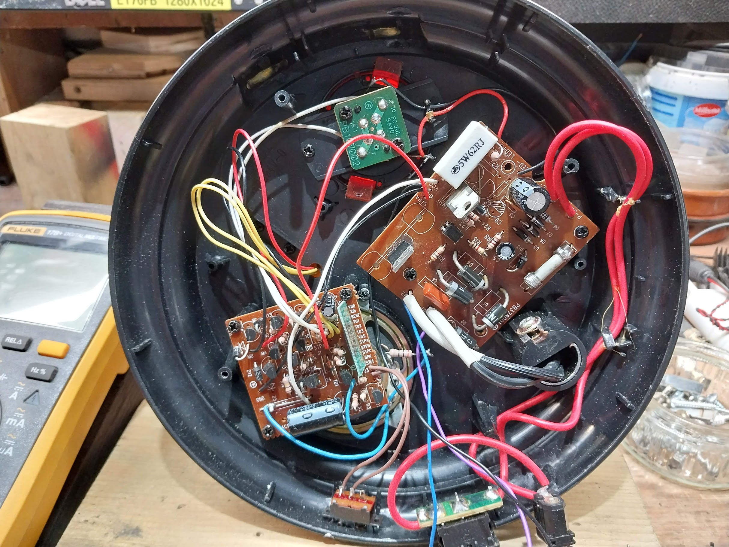
    When the light switch (single contact button) is operated the lamp makes an appropriate sound and a motor powered animation takes place. At the same time +5V is fed via a red wire (STPA) to the opto which in turn is connected to the MFET. I have tested the opto & MOSF off the board and test OK.

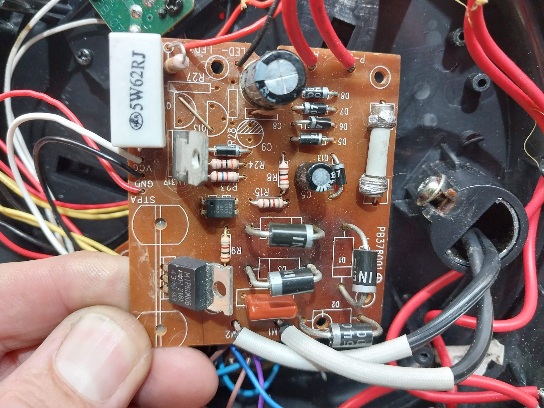
    I have also tested all the other components on the PS board: LM317 (7.96Vo/p), diodes, electrolytic, resistors but cannot get the lamp to switch on..
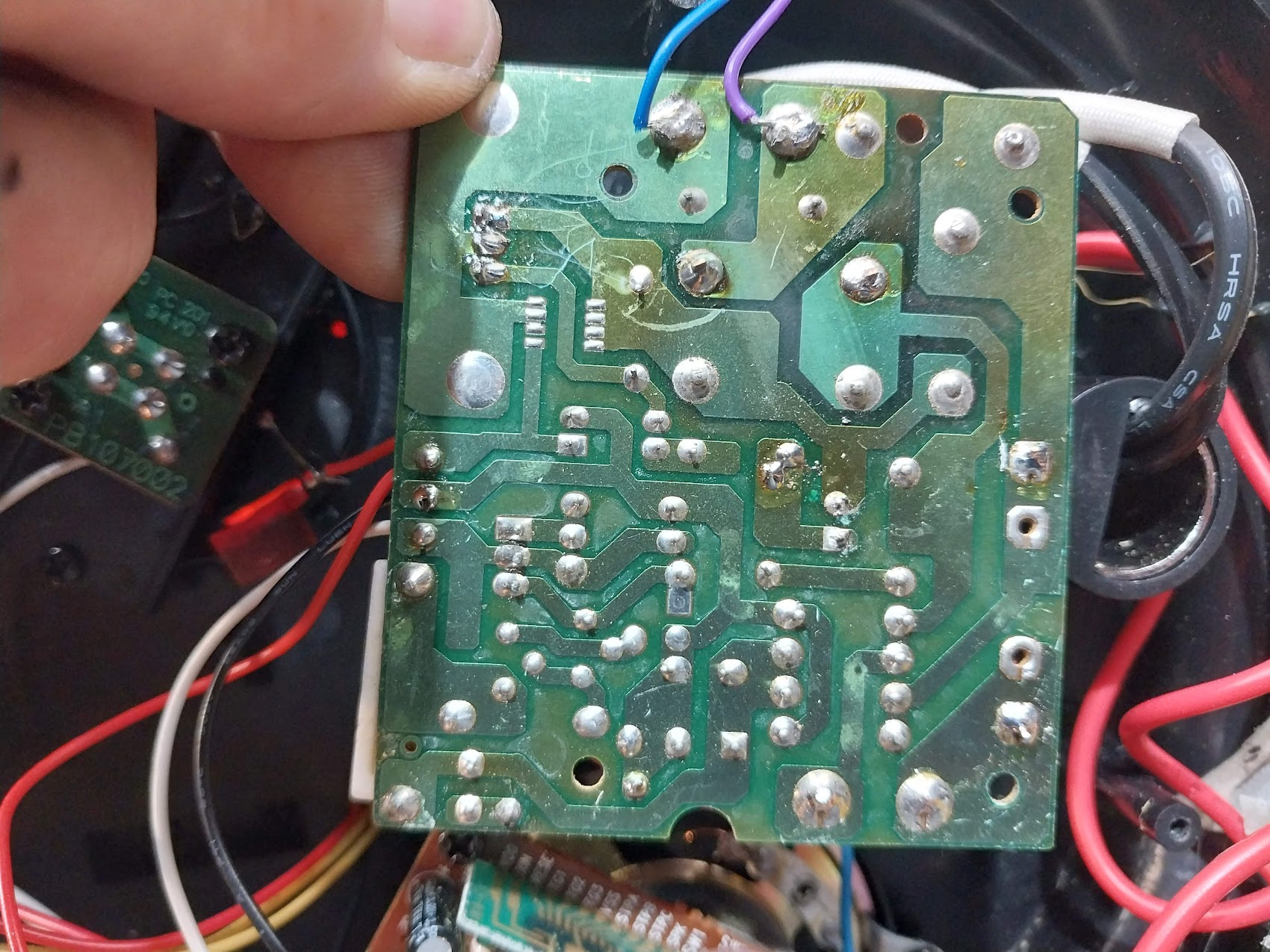
    There are 2 boards: one with the power supply, LM317 and the MFET. The second board has the animation & sound control, etc.

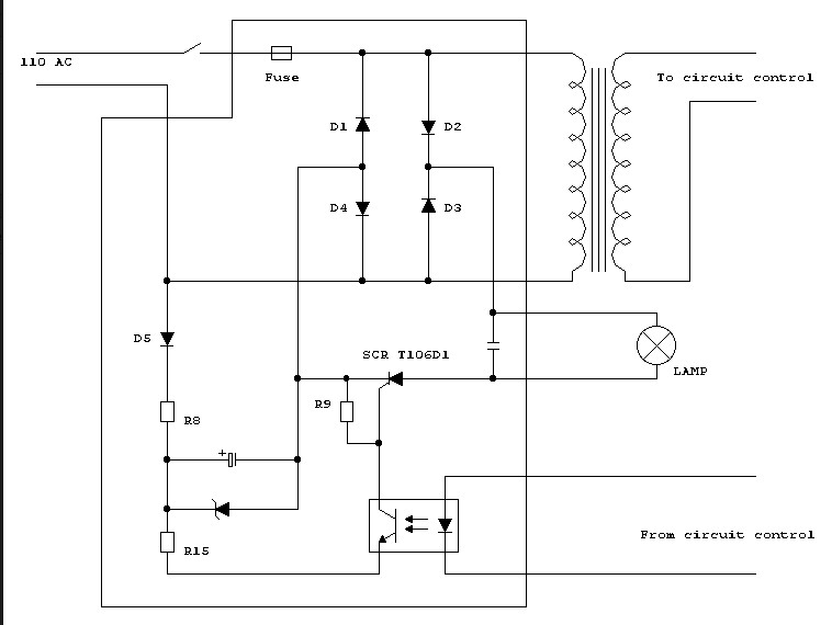
    The attached schematic is from a version of the light that has the mains transformer built in and a SCR for the lamp control.

    Any thoughts pointers would be great.

    Many thanks.


    Attached Files
    Last edited by Nevillet; 09-09-2022, 01:45 PM.

    #2
    Re: MOSFET controlled table light help please

    So, when you take a voltage reading with everything connected from the anode of D1 to the cathode of D2 you have 0 volts DC? Then switching to the AC volt range what do you read? 0 volts AC. Or do you have an Oscilloscope where you can just take a picture of what the O scope displays? Also, if you are using a digital meter to take the reading which meter are you using?

    Comment


      #3
      Re: MOSFET controlled table light help please

      check the fuse - soldering on to them like that can kill them,
      and check the ceramic resistor

      Comment


        #4
        Re: MOSFET controlled table light help please

        Hi Both,

        I'm using a Fluke 187 and a Siglent Scope.

        Measuring between D1A to D2K I measure the following:
        25.95V DC
        2.64V AC

        And here is the scope trace between the same points
        (probe end on D1A & earth end on D2K)


        The 5W ceramic resistor is good as is the ugly looking fuse bodge.
        Attached Files

        Comment


          #5
          Re: MOSFET controlled table light help please

          Stj has a good point on soldering. It is hard for me to tell from a picture but the black gnd. wire on the board did not look soldered correctly.

          Comment


            #6
            Re: MOSFET controlled table light help please

            What actual bulb does the lamp have in it and measuring across the lamp terminals what scope picture do you get? I'm eventually going to get to is the SCR not firing or is the control circuit that turns on the Opto isolator not turning it on. There should be a current draw through R9 to turn on the SCR. The SCR should stay on until it's forward threshold voltage becomes too low. D5 will only turn on in the positive side of the 110-acv wave form. D5 appears to be connecting a 1/2 wave regulator. That circuit has some sort of electrolytic with some sort of zener which must be regulating the voltage. So, the opto isolator will only conduct when D5 is allowed to conduct as otherwise the electrolytic cap will not charge. I am wondering about the opto isolator and NPN configuration? Seems the negative of the emitter is connected to a positive source. If this is correct, then I believe the opto isolator is connected as a common collector circuit. Where the collector/ base is the input, and the emitter is the output. The transistor can conduct this way but, it is a little unpredictable and rarely have I seen such connection other than mistakes. The R8 and R15 seem to be a voltage divider. Seems like the photo shows a 1K ohm, 5% resistors for R8, R15 and R9. The tolerance band appears to be gold in the picture.

            I will have to investigate the opto isolator in comparison to a actual transistor working. I believe the principles are the same however never sure of anything.
            Last edited by keeney123; 09-10-2022, 09:01 AM.

            Comment


              #7
              Re: MOSFET controlled table light help please

              oh i just had an idea.
              it's probably designed for a filament lamp - make sure nobody swapped-in an led replacement.
              it wont probably wont latch the scr.

              Comment


                #8
                Re: MOSFET controlled table light help please

                I have resoldered the black wire connecting the power board to the control board.

                I think I have added some confusion to the thread by posting the schematic above.
                The circuit I have does not have a SCR but instead a N-ch MOSFET.

                I do not have the correct 24V/50W lamp so have joined some power resistors together that total 14.4Ω with a parallel LED & series resistor to indicate the lamp has turned the bulb on.

                When the light is switched 'on' the red wire feeds the opto-isolator anode (+4.85V) with the cathode connected to ground.

                On the other side of the opto, the emitter is connected to the gate of the MOSF, the collector is connected to R15.

                The MOSF connections are:
                Gate - connected to the emitter of the opto
                Drain - connected to the lamp
                Source - connected to ground

                If i short the drain & source the lamp (resistor load) turns on.

                If I short the Col-Emit of the opto the lamp lights (which I guess means the MFET is OK?)
                Last edited by Nevillet; 09-10-2022, 11:38 AM.

                Comment


                  #9
                  Re: MOSFET controlled table light help please

                  Originally posted by Nevillet View Post
                  I have resoldered the black wire connecting the power board to the control board.

                  I think I have added some confusion to the thread by posting the schematic above.
                  The circuit I have does not have a SCR but instead a N-ch MOSFET.

                  I do not have the correct 24V/50W lamp so have joined some power resistors together that total 14.4Ω with a parallel LED & series resistor to indicate the lamp has turned the bulb on.

                  When the light is switched 'on' the red wire feeds the opto-isolator anode (+4.85V) with the cathode connected to ground.

                  On the other side of the opto, the emitter is connected to the gate of the MOSF, the collector is connected to R15.

                  The MOSF connections are:
                  Gate - connected to the emitter of the opto
                  Drain - connected to the lamp
                  Source - connected to ground

                  If i short the drain & source the lamp (resistor load) turns on.

                  If I short the Col-Emit of the opto the lamp lights (which I guess means the MFET is OK?)
                  So, what would be good is to simply hand draw the schematic to what you actually have connected and attach that schematic to this thread. List the values of the resistors etc. A schematic is much easier to follow than someone's explanation of what is connected in a circuit. If a schematic is made maybe me or another person can give you the theory of operation and explain what to look for at each point.

                  Comment


                    #10
                    Re: MOSFET controlled table light help please

                    I won't get back to the lamp for a few days so there will be a delay.

                    Many thanks for all your help.

                    Comment


                      #11
                      Re: MOSFET controlled table light help please

                      well now you know the output-side of the opto works,
                      i would temporarily replace the opto with a red led to see when it's driven
                      a bad opto wouldnt surprise me either

                      Comment


                        #12
                        Re: MOSFET controlled table light help please

                        The opto is a Cosmo K1010 (datasheet attached)

                        IF(mA) 50
                        Vceo(V) 80
                        IC (mA) 50
                        Viso(Vrms) 5000
                        VF max (V) 1.4
                        CTR% 50-600
                        VCE (sat) max (V ) 0.2
                        Tr (us) 4
                        Tf (us) 3

                        Can you suggest an equivalent?

                        My local suppliers are:
                        https://cpc.farnell.com/
                        https://uk.rs-online.com/web/

                        Attached Files

                        Comment


                          #13
                          Re: MOSFET controlled table light help please

                          probably a generic 817 or cny17
                          Attached Files

                          Comment


                            #14
                            Re: MOSFET controlled table light help please

                            Just to report back that the replacement 817 optocouplers arrived and fixed the problem.

                            It was interesting that the old opto worked - just not as well as the new replacement.

                            Many thanks for all your help.

                            Comment


                              #15
                              Re: MOSFET controlled table light help please

                              if you have a component tester based on the atmel mcu then you can use an adapter to test opto's

                              Comment


                                #16
                                Re: MOSFET controlled table light help please

                                Stj thanks for the help.

                                Comment

                                Working...
                                X