Announcement

Collapse
No announcement yet.

Fish Tank LED Power Supply Gets Hot then shuts down

Collapse
X
 
  • Filter
  • Time
  • Show
Clear All
new posts

    Re: Fish Tank LED Power Supply Gets Hot then shuts down

    Originally posted by stj View Post
    the panel may drive some leds from 12v and some from 5v to keep balance/
    so we need to look at them - also we are assuming they are white and not mixed colours
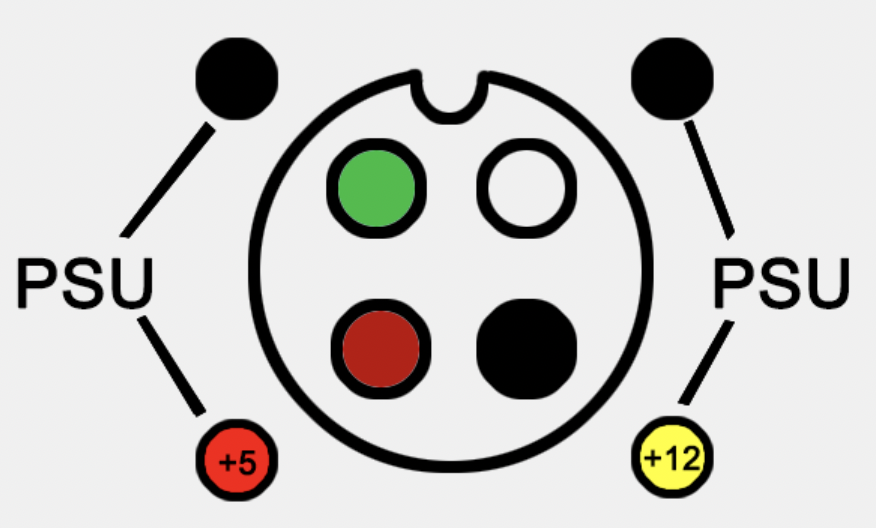
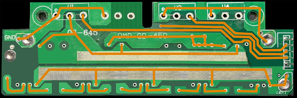
    Also ... just to make sure I'm clear on this ... it is of no immediate interest to you that the 5 volt line attaches where the red circle is on this photo and that it is the source of all the burning on the PCB that is also outlined in red? The same line that is drawing 5.5 amps?

    Comment


      Re: Fish Tank LED Power Supply Gets Hot then shuts down

      Originally posted by stj View Post
      the panel may drive some leds from 12v and some from 5v to keep balance/
      so we need to look at them - also we are assuming they are white and not mixed colours
      Just got a bunch of caps imma replace all of them on that main controller board ... whether or not they're bad ... figured it couldn't hurt.

      Comment


        Re: Fish Tank LED Power Supply Gets Hot then shuts down

        if that driver board shorts to the screws or mounts your gonna ground the power and burn a wire!

        Comment


          Re: Fish Tank LED Power Supply Gets Hot then shuts down

          I say you've got a ground-fault, meaning DC power somehow got shorted to the grounded chassis. Get out the ohmmeter and hunt it down.
          Anywhere any PC board could short to the chassis has to be checked. The short-circuit could vanish as you take things apart, so it's best to first stake continuity measurements before trying to figure out the schematic.

          I would say it's doing linear current control of LED brightness, and LED+ goes to power. So an LED short to heatsink could do it, make sure the heatsinks end up isolated.
          Also the power transistor PC board's cardboard insulating mounting washers, those don't age/take humidity well.

          The double splices with red heatshrink, hopefully done properly but don't trust that workmanship. Someone else has been in here doing "fixes". The fuse wire could also have been caused by an open-circuit - an open ground and the boards ended up pulling current through the small connectors and controller board. But you read 5.5A on 5V so more likely to have a short somewhere.

          One strip says "Blue" so 5 LED's on a board must be the same colour (block) but why they have 4 wires to each LED board is a bit weird. That would be for individual colour control on each channel. Are these LED strings on a board in series? Hopefully not over 12V... if so then we know why this has strange power wiring.

          The 7805(-) wire fried on the controller, and it has roasted PC board traces; tracing that overcurrent is a bit weird again. In the pic of the controller board you see the large trace overheated yet none of the little ones fanning out from it to the connectors cooked or melted.
          So where did the ground current end up going to?

          Comment


            Re: Fish Tank LED Power Supply Gets Hot then shuts down

            So the plot thickens ... a little ...

            Here is the schematic of ONE of the 5 LED strips ... on the PCB, it says that it is 5 - 3 BLUE


            The 5 - 3 might mean that LED 5 is Blue and that there are three blues on the PCB because LEDs 1, 3, and 5 are BLUE and LEDs 2 and 4 are a white / yellowish color.

            They seem to power just fine with 3 volts at 100ma so 9 volts @ 100ma for the series LEDs and 3 volts at 200 ma for the parallel set worked perfectly.

            The other type of LED strip PCB is wired the exact same way, only difference are the colors.

            On the PCBs that say 5 - 3 C, in the odd numbered LEDs, 1 and 5 are that white / yellowish color with the center LED (3) being CYAN and the two parallel LEDs (2 and 4) are both blue so on those strips, we have


            White - Blue - Cyan - Blue - White

            And on the first PCB we have

            Blue - White - Blue - White - Blue

            Now, I only drove these at 3 volts. They could very well be 4.x volt LEDs at which point it would require 12 Volts to drive the series LEDs and the 5 volts could drive the parallel LEDs. They could be connecting the MOSFETs in pairs where each pair is dedicated to the entire set of 5 rows, one pair switches in the 12 volts for the series LEDs the other pair of MOSFETs would be driving all of the parallel paired LEDs using the 5 volt line from the PSUs.

            That makes the most sense to me anyways.

            The alternative could be that they are 3.2 volt LEDs and that the controller board never pushes the MOSFETs into full saturation.

            OK, now - I took out one of the LED driver boards and am going through it, but where the connectors to each LED strip are concerned, this is how they are all wired in relation to each other on the PCB they connect to.


            The Black and green on the edges of each connector are all wired together on all five connectors. But the Yellows and Reds are only connected together for three of the strips and the two offset strips have their Red and Yellow wires connected to each other.


            Last edited by EasyGoing1; 10-16-2022, 12:22 AM.

            Comment


              Re: Fish Tank LED Power Supply Gets Hot then shuts down

              outside pair are anodes, inside are cathodes

              it probably has it split to reduce load on the mosfets that i assume switch the cathodes.
              draw up the rest of the fet circuits

              Comment


                Re: Fish Tank LED Power Supply Gets Hot then shuts down

                Originally posted by stj View Post
                outside pair are anodes, inside are cathodes

                it probably has it split to reduce load on the mosfets that i assume switch the cathodes.
                draw up the rest of the fet circuits
                Scratch what I said on the driver board PCB. The resistors are only .3Ω so my meter was picking up those connections as a short ... but I've almost got the full schematic for the driver boards ... ill be posting that shortly.

                Comment


                  Re: Fish Tank LED Power Supply Gets Hot then shuts down

                  Here is the LED Driver board schematic ... this shit is kinda WHACK if you ask me.


                  Last edited by EasyGoing1; 10-16-2022, 07:10 AM.

                  Comment


                    Re: Fish Tank LED Power Supply Gets Hot then shuts down


                    I was also wrong about the power feed from the PSU to the main controller board. The hotline going to the main controller board is +12, and the black wire is ground from the PSU.

                    What's been so confusing this whole time is that the cables they use to connect to the PSU are not the same color wires as the wires inside the PSU.

                    But this is how they actually map out, and the melted wires going to the main controller board are red and black, where Red is connected to the black wire which is +12 from the PSU and black is connected to the white wire, which is GND from the PSU:


                    Last edited by EasyGoing1; 10-16-2022, 07:12 AM.

                    Comment


                      Re: Fish Tank LED Power Supply Gets Hot then shuts down


                      And for anyone interested ...

                      Here is the front side of the PCB with its traces connected with orange lines


                      And here is the back of the PCB in mirror image with its traces connected with yellow lines


                      Here is the front PCB image again with both front and back traces


                      And here is the PCB with all traces, resistors and labels


                      And here is the schematic with the LEDs properly labeled in their respective colors


                      Last edited by EasyGoing1; 10-16-2022, 08:06 AM.

                      Comment


                        Re: Fish Tank LED Power Supply Gets Hot then shuts down

                        load balanced between the 5v and 12v - not bad.

                        Comment


                          Re: Fish Tank LED Power Supply Gets Hot then shuts down

                          Originally posted by stj View Post
                          load balanced between the 5v and 12v - not bad.
                          But does this get us any closer to a solution?

                          Comment


                            Re: Fish Tank LED Power Supply Gets Hot then shuts down

                            Disconnect boards one at a time until the 5A stops being 5A ... ?

                            Comment


                              Re: Fish Tank LED Power Supply Gets Hot then shuts down

                              Originally posted by stj View Post
                              load balanced between the 5v and 12v - not bad.
                              I'm not sure what you consider balanced, but based on the current draw that I used to light up a row of LEDs, here is the load that would be placed on each transistor


                              In fact, I threw the circuit into a simulator and though I know the values aren't accurate, the LEDs are all set the same and clearly you can see that Q4 is the redheaded step child in this family...

                              Last edited by EasyGoing1; 10-17-2022, 01:15 AM.

                              Comment


                                Re: Fish Tank LED Power Supply Gets Hot then shuts down

                                i think the fault was one of those big power tracks shorting to the frame or a screw

                                Comment


                                  Re: Fish Tank LED Power Supply Gets Hot then shuts down

                                  Originally posted by stj View Post
                                  i think the fault was one of those big power tracks shorting to the frame or a screw
                                  See, I would agree with that if not for the long melted wire and all the burn marks on the master control board... clearly, an indication that something on that board was drawing too much current.

                                  Also, given the way these LEDs are wired, I'm wondering if seeing 5 amps on the 5-volt line is really all that abnormal in this circuit.

                                  Also, the burnt wire and fried board was all sourced from the +12 but then regulated down to +5 where the burn marks were around the regulator then on the opposite end of the board along the ground strip next to an op amp chip and two digital pot chips. The op amp chip drives the gates of the LED driver boards.

                                  On the flip side of that burnt ground strip, +12 runs along that same edge and feeds the housing fans directly which are controlled via the microcontroller with a simple transistor switch, emitter to ground, base to MC through resistor and collector directly wired to the fans negative side and the positive side of the fans go directly to +12.

                                  Also they only use one transistor for two fans and they're only S8050s.

                                  Something else I learned is at the controller board, the pins that drive the gates ... are all connected in parallel ... this board has 6 separate connectors for the LED driver boards and on all of them, all pin 1s are connected, all pin 2s etc. etc. so each gate gets the same applied voltage on all driver boards, which Im sure just gives uniform brightness etc.

                                  I replaced the caps on the main controller board and now that I know it's powered by +12, I'm going to connect 12 volts to it and see what kind of current its drawing. Though the housing fans are not connected and neither are the LEDs but maybe it will show me something useful. If the magic smoke doesn't start leaking ill take some readings around the board and see whats going on.

                                  Comment


                                    Re: Fish Tank LED Power Supply Gets Hot then shuts down

                                    So, given how this thing is actually wired up, does anyone see a problem with me wiring it for a single 1,000W PS vs two 500W PSUs as it is now?

                                    Comment


                                      Re: Fish Tank LED Power Supply Gets Hot then shuts down

                                      Seems to me this would have been a better design for this unit vs what it is now.

                                      Comment


                                        Re: Fish Tank LED Power Supply Gets Hot then shuts down

                                        i think you probably dont need more than 500w - real 500w that is, not the inflated BS on a lot of psu labels
                                        did you check all the fans for current draw?

                                        Comment


                                          Re: Fish Tank LED Power Supply Gets Hot then shuts down

                                          Originally posted by stj View Post
                                          i think you probably dont need more than 500w - real 500w that is, not the inflated BS on a lot of psu labels
                                          did you check all the fans for current draw?
                                          I did, and what is interesting is that I can't get them all to run off of the main controller board - it seems like two of the four fan ports wont power the fans so imma check for voltage but I know the microcontroller is working because at least two of the ports work and if the other ones don't have voltage then its probably the transistor or something ... gonna dig into that now.

                                          When I connect the fans directly to the bench power supply only three of them work ... they are old and have taken obvious moisture wear as there are some kind of crud deposits built up around them ...

                                          I'm ordering two of these to replace all four.

                                          Other than that, I can't find anything wrong with this thing ... so I've ordered replacement heat transfer pads for the transistors, plus a tube of thermal grease for the LEDs where they attach to the main heat sink ... the grease that's on there now is 20 years old so cleaning it all up and replacing that seems like the right choice ... and I'm just gonna tap the solder connections and maybe add a touch of leaded solder to them just to make sure there are no cracked solder points then ill put everything back together and make sure everything is completely away from any potential ground points and see what happens.

                                          Comment

                                          Working...
                                          X