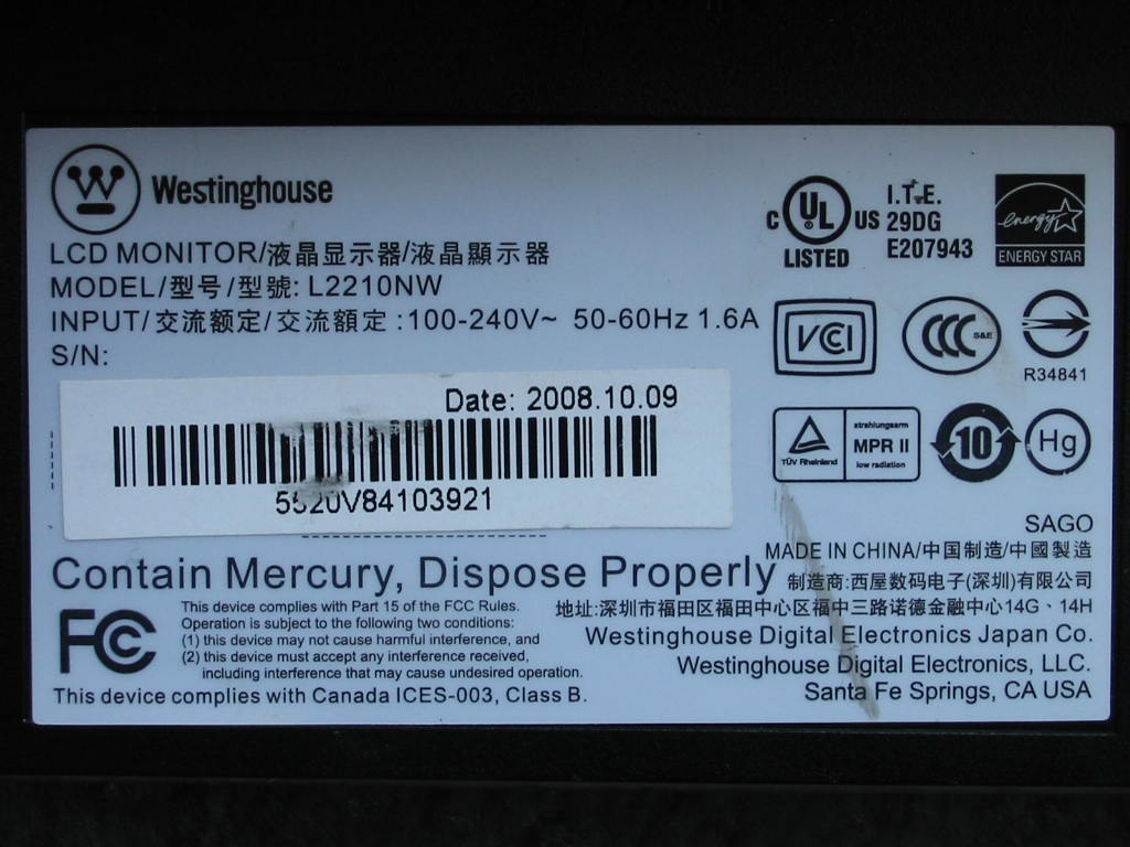
Here's another LCD monitor repair: Westinghouse L2210NW.
Quick specs: 22” CCFL backlit LCD, 1680x1050 max resolution (16:10 aspect ratio)
I got it with a bunch of desktops PCs from a repair shop that was trying to free up space a few years ago. It seemed like a cheap monitor, so I didn't really care that much at first when I picked it up (and indeed it is, picture-wise.) But hey, free is free, so I can't complain. Moreover, it looked clean and the screen didn't have any significant scratches or blemishes.
Pictures of the monitor outside/case after a brief cleaning:
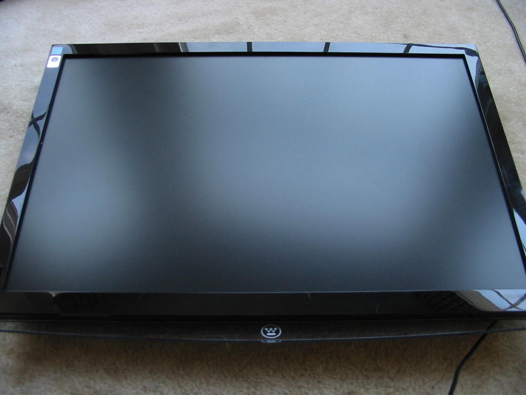
Overall, it looks pretty good and seemed worth a shot at repair. (And yes, it did come with a stand - I just didn't have it in the picture.)
When plugged in, the LED indicator light didn't come on and the monitor emitted a squealing noise. The backlights didn't work either (or even flash, for that matter.) Classic bad cap problem in the PSU?
Time to tear it open:
https://www.badcaps.net/forum/attach...1&d=1610348960
https://www.badcaps.net/forum/attach...1&d=1610348960
I forgot to take a picture with the metal back cover, but it was pretty small and made to fit exactly just the PSU and logic board - not much spare room for breathing/cooling. On top of that, the metal cover wasn't held with any screws to the LCD panel chassis, either - just taped with aluminum conductive tape. A metal shield over the T-con board also isn't installed (and this monitor didn't appear to have been opened before, so I think it came like that from the factory.) If anyone is thinking this is cheapo low-end LCD monitor, you're exactly right. Panel is made by Chi Mei, too… which I think is probably a good price match with the rest of the build quality.
Anyways, let's take a look at the problem: bad caps on the PSU board, indeed.
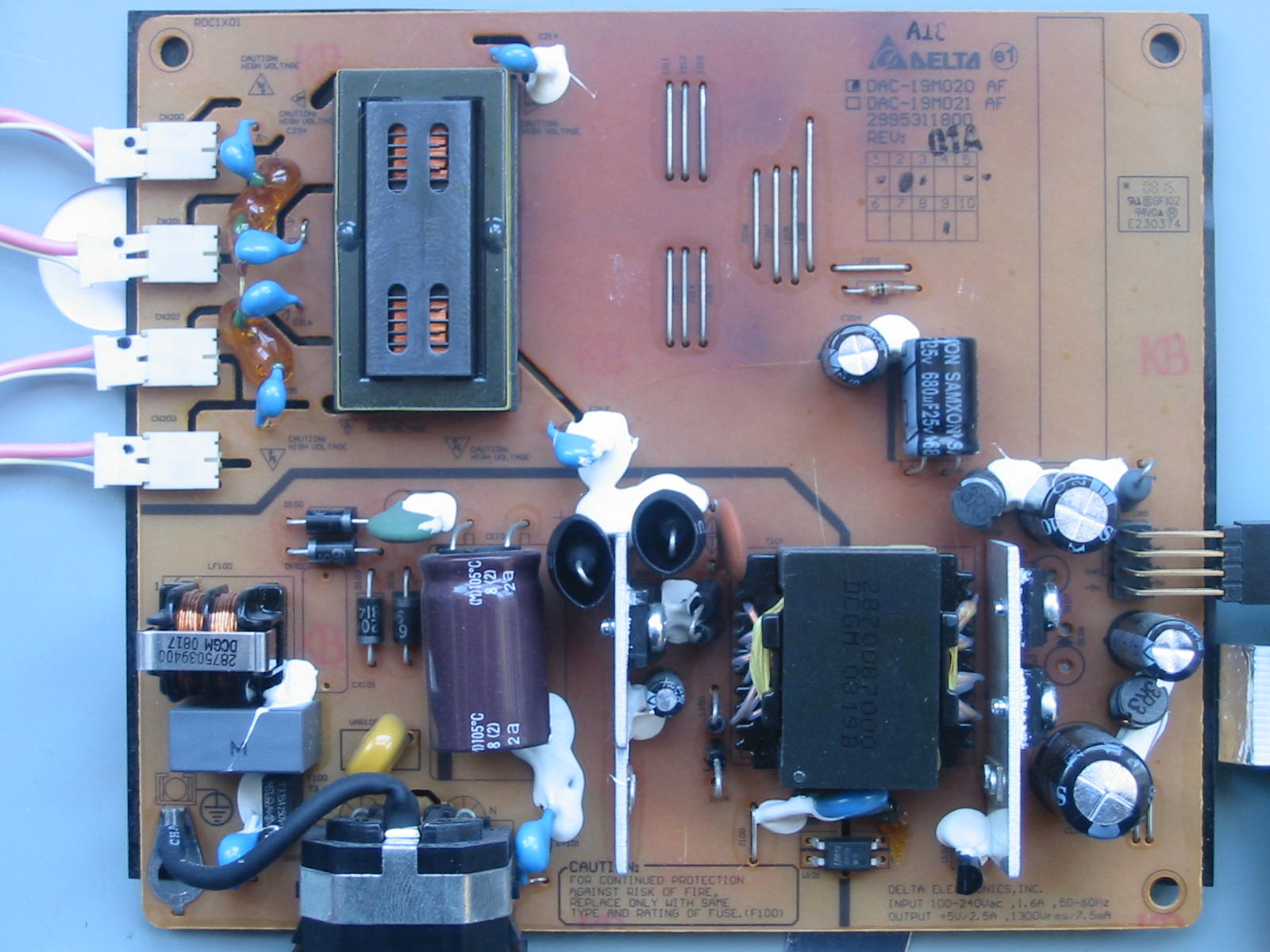
The offender here was actually just a single Samxon SF 10V, 2200 uF cap. The other four Samxon SF caps checked out fine. Not that I wouldn't recap them, though (full cap list can be found a little further below), since the PCB indicated a few hot spots, judging by the darkened areas (perhaps one good thing Phenolic PCBs are good for.)
Here you can see the hot spots on the solder side of the PCB too.
https://www.badcaps.net/forum/attach...1&d=1610348960
https://www.badcaps.net/forum/attach...1&d=1610348960
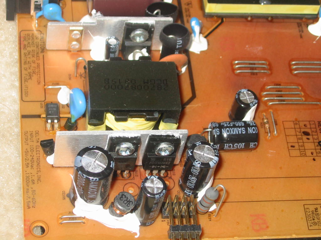
The inverter transformer seems to have taken the most abuse. Its driving transistors weren't that far behind, though, and probably ran quite toasty too.
Given the heat, I wanted to make sure the monitor works before investing too much time and new caps into it. As a test, I recapped only the single bad Samxon SF 10V, 2200 uF cap with a Taicon PW 10V, 2200 uF cap. Not surprisingly, the monitor came back to life after that (backlights and all). So, time for a recap!
---------- Cap List ----------
List of all the electrolytic capacitors found on the L2210NW power supply board (excluding the big primary cap):
CE101: Samxon SF, 35V, 33 uF, 5 x 11 mm <-- “start-up” cap, primary side
CE102: Samxon SF, 25V, 1000 uF, 10 x 20 mm <-- Vcc for inverter, 1st filter cap
CE104: Samxon SF, 25V, 680 uF, 10 x 16 mm <-- Vcc for inverter, 2nd filter cap
C204: Samxon SF, 25V, 220 uF, 8 x 12 mm <-- Vcc for inverter, 3rd filter cap
CE105: Samxon SF, 10V, 2200 uF, 12.5 x 20 mm <-- 5V rail, 1st filter cap
CE106: Samxon SF, 10V, 1000 uF, 8 x 20 mm <-- 5V rail, 2nd filter cap
Note 1: Vcc for the inverter can peak and/or go slightly above 16V when the monitor is in standby / soft-off mode and the inverter is not drawing any power. Therefore, DO NOT use 16V -rated caps for CE102, CE104, and C204. These caps should be rated for 25V. I already thought about taking this “short-cut” due to being out of stock on a few 25V cap values… but I'm glad I decided to measure the Vcc for the inverter. It appears this rail is either not monitored by the PSU feedback circuits or just not weighted too much in the regulation, because it swings quite a bit when the inverter is on (dips below 13-15V) or off (can peak above 16V.) On the other hand, the 5V rail is monitor and quite steady around 5V.
Note 2: cap height is limited to 25 mm. With that said, I DO NOT recommend that 25 mm high cap be fitted - at least not vertically (horizontally / cap laid on its side - OK!) Reason being is that from what I remember measuring, the vent on a 25 mm high cap will be right up against the metal back cover that houses the PSU and logic boards… and obviously that's not a good idea, should any pressure build up inside the cap for some reason.
Note 3: Samxon SF datasheet does not have an entry for a 25V, 680 uF cap in 10 x 16 mm size. So when looking for ESR/impedance and ripple current specs, I just used the data for a 10 x 16 mm cap in the SF datasheet for a 25V cap (in this case, 25V, 470 uF). Same applies for the 25V, 1000 uF Samxon SF in 10 x 20 mm. Datasheet states this must be a 12.5 x 20 mm cap. So for impedance and RC specs, I used 10 x 20 mm size.
With that said, here is how I did my recap:
CE101 was replaced with a Rubycon YXJ of same V and uF.
CE102 was replaced with a Rubycon YXJ of same V and uF.
CE104 was replaced with a United Chemicon LXY (or LXV?) 25V, 1000 uF (note: this is a 25 mm -high cap that I placed horizontally / on its side to make it fit.)
C204 was replaced with the old cap from spot CE104: Samxon SF, 25V, 680 uF, 10 x 16 mm. Yes, I guess you can say I didn't really do a “full” recap") … but that's because I didn't have any appropriate 25V caps left. It shouldn't matter, though, because CE102 and CE104 pretty much do the majority of the filtering on the inverter Vcc rail.
… but that's because I didn't have any appropriate 25V caps left. It shouldn't matter, though, because CE102 and CE104 pretty much do the majority of the filtering on the inverter Vcc rail.
CE105 was replaced with a Rubycon ZLH rated for 6.3V and same 2200 uF capacity. (The original Samxon SF here had a 10V rating. But I found the 5V rail is regulated quite well, so a 6.3V cap could be used - which I did due to cap stock reasons.)
CE106 was replaced with a United Chemicon KY rated for 6.3V and same 1000 uF capacity. (The original Samxon SF here had a 10V rating. But I found the 5V rail is regulated quite well, so a 6.3V cap could be used.)
Quick specs: 22” CCFL backlit LCD, 1680x1050 max resolution (16:10 aspect ratio)
I got it with a bunch of desktops PCs from a repair shop that was trying to free up space a few years ago. It seemed like a cheap monitor, so I didn't really care that much at first when I picked it up (and indeed it is, picture-wise.) But hey, free is free, so I can't complain. Moreover, it looked clean and the screen didn't have any significant scratches or blemishes.
Pictures of the monitor outside/case after a brief cleaning:
Overall, it looks pretty good and seemed worth a shot at repair. (And yes, it did come with a stand - I just didn't have it in the picture.)
When plugged in, the LED indicator light didn't come on and the monitor emitted a squealing noise. The backlights didn't work either (or even flash, for that matter.) Classic bad cap problem in the PSU?
Time to tear it open:
https://www.badcaps.net/forum/attach...1&d=1610348960
https://www.badcaps.net/forum/attach...1&d=1610348960
I forgot to take a picture with the metal back cover, but it was pretty small and made to fit exactly just the PSU and logic board - not much spare room for breathing/cooling. On top of that, the metal cover wasn't held with any screws to the LCD panel chassis, either - just taped with aluminum conductive tape. A metal shield over the T-con board also isn't installed (and this monitor didn't appear to have been opened before, so I think it came like that from the factory.) If anyone is thinking this is cheapo low-end LCD monitor, you're exactly right. Panel is made by Chi Mei, too… which I think is probably a good price match with the rest of the build quality.
Anyways, let's take a look at the problem: bad caps on the PSU board, indeed.
The offender here was actually just a single Samxon SF 10V, 2200 uF cap. The other four Samxon SF caps checked out fine. Not that I wouldn't recap them, though (full cap list can be found a little further below), since the PCB indicated a few hot spots, judging by the darkened areas (perhaps one good thing Phenolic PCBs are good for.)
Here you can see the hot spots on the solder side of the PCB too.
https://www.badcaps.net/forum/attach...1&d=1610348960
https://www.badcaps.net/forum/attach...1&d=1610348960
The inverter transformer seems to have taken the most abuse. Its driving transistors weren't that far behind, though, and probably ran quite toasty too.
Given the heat, I wanted to make sure the monitor works before investing too much time and new caps into it. As a test, I recapped only the single bad Samxon SF 10V, 2200 uF cap with a Taicon PW 10V, 2200 uF cap. Not surprisingly, the monitor came back to life after that (backlights and all). So, time for a recap!
---------- Cap List ----------
List of all the electrolytic capacitors found on the L2210NW power supply board (excluding the big primary cap):
CE101: Samxon SF, 35V, 33 uF, 5 x 11 mm <-- “start-up” cap, primary side
CE102: Samxon SF, 25V, 1000 uF, 10 x 20 mm <-- Vcc for inverter, 1st filter cap
CE104: Samxon SF, 25V, 680 uF, 10 x 16 mm <-- Vcc for inverter, 2nd filter cap
C204: Samxon SF, 25V, 220 uF, 8 x 12 mm <-- Vcc for inverter, 3rd filter cap
CE105: Samxon SF, 10V, 2200 uF, 12.5 x 20 mm <-- 5V rail, 1st filter cap
CE106: Samxon SF, 10V, 1000 uF, 8 x 20 mm <-- 5V rail, 2nd filter cap
Note 1: Vcc for the inverter can peak and/or go slightly above 16V when the monitor is in standby / soft-off mode and the inverter is not drawing any power. Therefore, DO NOT use 16V -rated caps for CE102, CE104, and C204. These caps should be rated for 25V. I already thought about taking this “short-cut” due to being out of stock on a few 25V cap values… but I'm glad I decided to measure the Vcc for the inverter. It appears this rail is either not monitored by the PSU feedback circuits or just not weighted too much in the regulation, because it swings quite a bit when the inverter is on (dips below 13-15V) or off (can peak above 16V.) On the other hand, the 5V rail is monitor and quite steady around 5V.
Note 2: cap height is limited to 25 mm. With that said, I DO NOT recommend that 25 mm high cap be fitted - at least not vertically (horizontally / cap laid on its side - OK!) Reason being is that from what I remember measuring, the vent on a 25 mm high cap will be right up against the metal back cover that houses the PSU and logic boards… and obviously that's not a good idea, should any pressure build up inside the cap for some reason.
Note 3: Samxon SF datasheet does not have an entry for a 25V, 680 uF cap in 10 x 16 mm size. So when looking for ESR/impedance and ripple current specs, I just used the data for a 10 x 16 mm cap in the SF datasheet for a 25V cap (in this case, 25V, 470 uF). Same applies for the 25V, 1000 uF Samxon SF in 10 x 20 mm. Datasheet states this must be a 12.5 x 20 mm cap. So for impedance and RC specs, I used 10 x 20 mm size.
With that said, here is how I did my recap:
CE101 was replaced with a Rubycon YXJ of same V and uF.
CE102 was replaced with a Rubycon YXJ of same V and uF.
CE104 was replaced with a United Chemicon LXY (or LXV?) 25V, 1000 uF (note: this is a 25 mm -high cap that I placed horizontally / on its side to make it fit.)
C204 was replaced with the old cap from spot CE104: Samxon SF, 25V, 680 uF, 10 x 16 mm. Yes, I guess you can say I didn't really do a “full” recap
… but that's because I didn't have any appropriate 25V caps left. It shouldn't matter, though, because CE102 and CE104 pretty much do the majority of the filtering on the inverter Vcc rail.CE105 was replaced with a Rubycon ZLH rated for 6.3V and same 2200 uF capacity. (The original Samxon SF here had a 10V rating. But I found the 5V rail is regulated quite well, so a 6.3V cap could be used - which I did due to cap stock reasons.)
CE106 was replaced with a United Chemicon KY rated for 6.3V and same 1000 uF capacity. (The original Samxon SF here had a 10V rating. But I found the 5V rail is regulated quite well, so a 6.3V cap could be used.)
Attached Files


 I soldered a small length to each regulator’s tab, and that was that.
Comment