When I got this motherboard it had some bulged capacitors but worked. One day, after some intensive CPU testing, it died peacefully.
Since I enjoy learning about electronics and repairing things, I decided to recap it. Got a 60W soldering iron and a few other things and I took note of the position and values of the capacitors on the motherboard:
10 1200uF 6.3v
19 330uF 25v
3 22uF 16v
But after desoldering all caps, I noticed I made a mistake, as one of the 3 smaller capacitors is 4.7 uF/50v instead of 22uF. I guess I didn't see clearly before desoldering. Now I wonder where this 4.7uF/50v is supposed to go.
My best guess based on some (not-so-clear) pictures I took before desoldering is that the 4.7uF 50v capacitor goes in the middle of the other two, i.e:
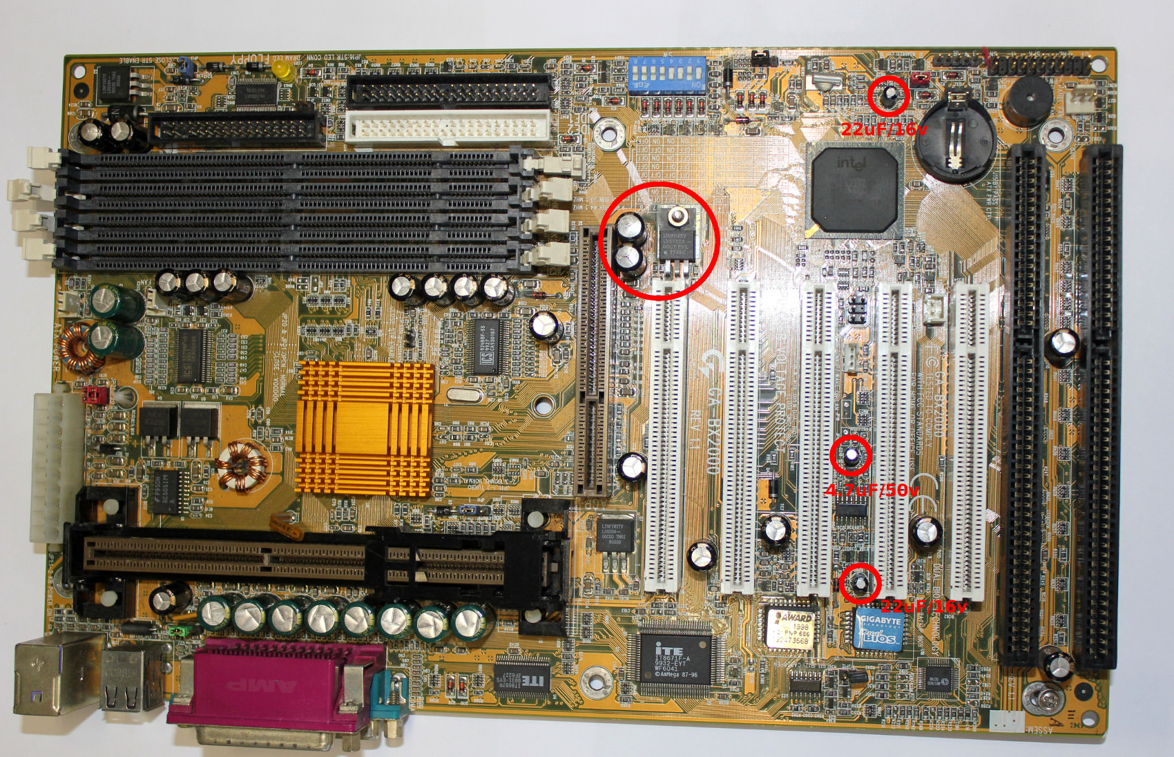
Can somebody with this motherboard please confirm this?
So if this is right, the correct count of the aluminum electrolytic capacitors is:
10 1200uF 6.3v
19 330uF 25v
2 22uF 16v
1 4.7uF 50v
I have another issue, this one apparently is the definitive issue.
I noticed the capacitors near the voltage regulator in the center (LINFINITY LX8383A - 00CP PHIL 9935C), (datasheet) were bulged, and the bottom of the PCB right under the voltage regulator looks discolored. So maybe this means the LX8383A is bad too? or this discoloration maybe was caused by the bad caps nearby?


If the voltage regulator is bad, what replacement should I buy? What are the alternatives?
I tried to understand the datasheet, I noticed this isn't a fixed voltage regulator and it needs a capacitor. But honestly I couldn't understand much.
Thank you for sharing your knowledge
Since I enjoy learning about electronics and repairing things, I decided to recap it. Got a 60W soldering iron and a few other things and I took note of the position and values of the capacitors on the motherboard:
10 1200uF 6.3v
19 330uF 25v
3 22uF 16v
But after desoldering all caps, I noticed I made a mistake, as one of the 3 smaller capacitors is 4.7 uF/50v instead of 22uF. I guess I didn't see clearly before desoldering. Now I wonder where this 4.7uF/50v is supposed to go.
My best guess based on some (not-so-clear) pictures I took before desoldering is that the 4.7uF 50v capacitor goes in the middle of the other two, i.e:
Can somebody with this motherboard please confirm this?
So if this is right, the correct count of the aluminum electrolytic capacitors is:
10 1200uF 6.3v
19 330uF 25v
2 22uF 16v
1 4.7uF 50v
I have another issue, this one apparently is the definitive issue.
I noticed the capacitors near the voltage regulator in the center (LINFINITY LX8383A - 00CP PHIL 9935C), (datasheet) were bulged, and the bottom of the PCB right under the voltage regulator looks discolored. So maybe this means the LX8383A is bad too? or this discoloration maybe was caused by the bad caps nearby?
If the voltage regulator is bad, what replacement should I buy? What are the alternatives?
I tried to understand the datasheet, I noticed this isn't a fixed voltage regulator and it needs a capacitor. But honestly I couldn't understand much.
Thank you for sharing your knowledge
Attached Files


Comment