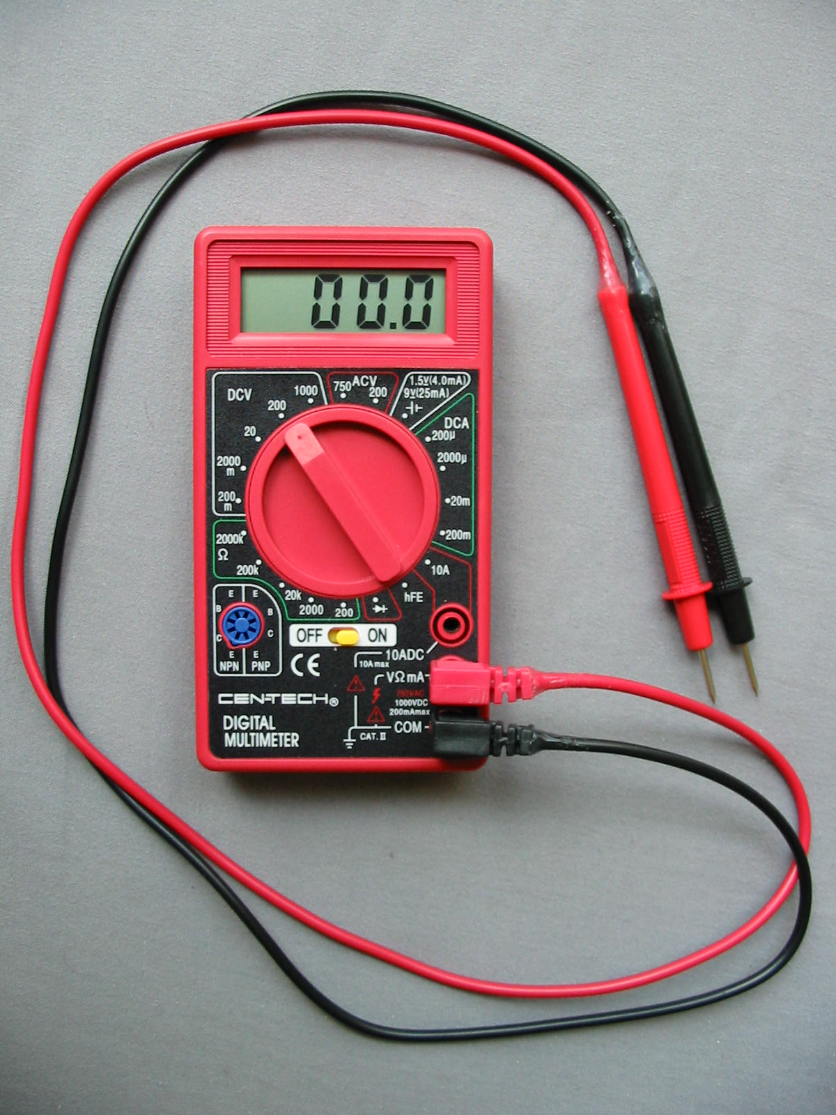
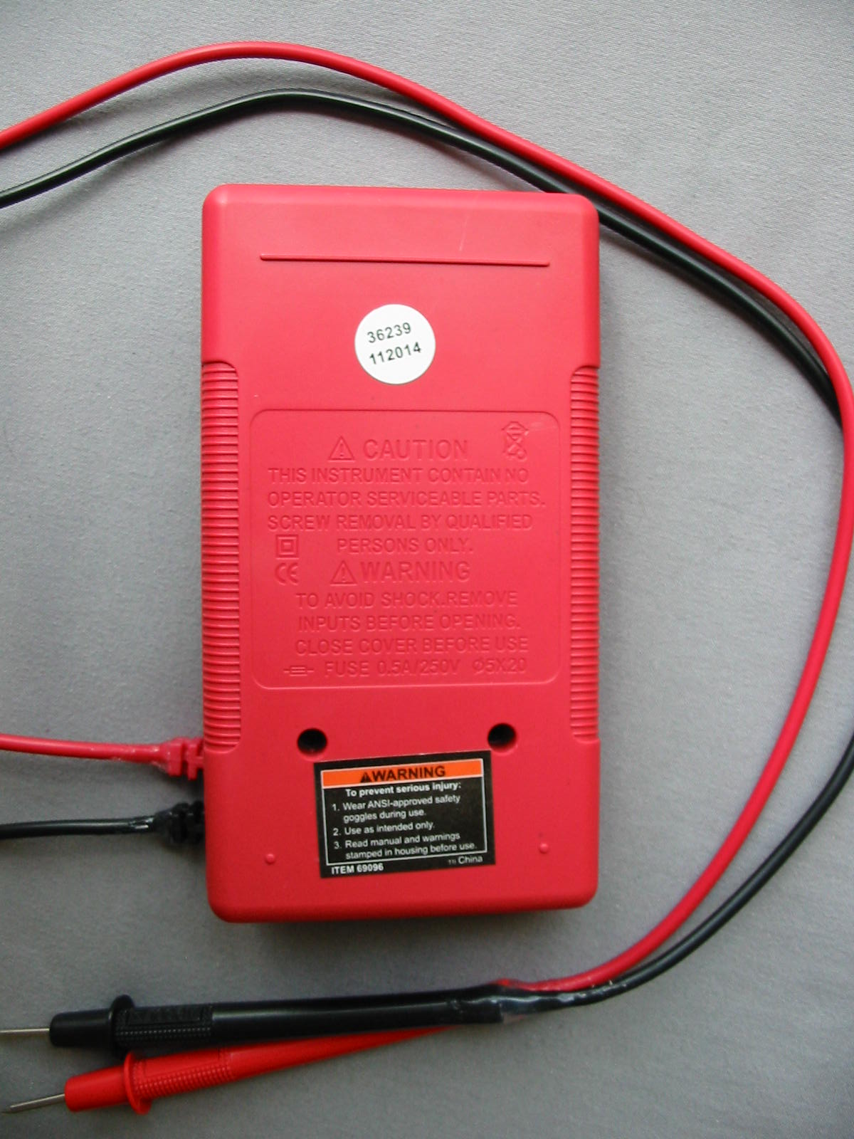
Two months ago, I received coupons from HF, and one of them included this meter for free (with any purchase). Since I needed some other stuff from there, I went and also grabbed this digital multimeter. The unit I got is item # 69096.
I didn’t really expect much, since even without the coupons, this multimeter is regularly sold for under $10.
It’s a very plain 7-function multimeter: standard AC and DC voltage measurements, DC current up to 200 mA or 10A, up to 2 MOhms resistance, diode test, transistor hFE, and 1.5V/9V battery test. Note, however, that there is no continuity function (hence no buzzer either).
Probably one of its better-thought features is that it has a separate ON-OFF button – or at least I like it better, since I can leave the dial on a setting that’s used the most and not have to turn the dial when I want to turn the multimeter OFF.
Before tearing the multimeter open, I decided to test some of its capabilities. Upon trying to plug the probes in the multimeter, I noticed that they didn’t go in quite easily. The 10A jack was particularly stubborn – I couldn’t plug in the probe all the way no matter how much pressure I applied (and I didn’t want to apply too much as I didn’t want to break anything after all). I inspected the plugs on the probes, but they appeared fine. So most likely something was obstructing the jacks in the multimeter.
Speaking of the probes, they appeared quite thin - but no less than the ones on my 13-year-old 830 multimeter. Same length, too. Even the handles were nearly identical, with the wires running through them and not held by anything at the end to prevent them from being twisted in the handle (which, over time will cause the wires to break away from the handles).
…
Continuing with my tests, I dialed the 200 Ohm setting and turned on the multimeter. I got a “1” on the left side of the screen – a good sign so far. Next, I shorted the probes together with a 16 AWG jumper lead. The display showed “14”. I though, that’s a bit high, isn’t it? Then I picked up the multimeter and tried to turn its dial. All of a sudden, a dot appeared between the two digits, thus showing “1.4”, then disappeared again. A-ha! So the decimal point isn’t working.
Next I tested a voltage on a battery and compared it to my other multimeters. It agreed, so I concluded that’s enough testing and tore it up .
.
Build quality:
With a half-working decimal point on the display and probes that didn’t plug in the jacks very well, it is clear that the build quality wouldn’t be great. But I’ll let the pictures speak for themselves. First, here is a shot of the solder-side:
https://www.badcaps.net/forum/attach...1&d=1406841775
Not too bad at first sight, it seems – and it really isn’t. However, note the small PCB that holds the jacks for the probes – it is held to the other board only with big, blobby solder joints. I can see a lot of potential (pun intended) for trouble there.
The solder joints on the rest of the board are pretty blobby too. The fuse (missing in the pictures, because I removed it) is a standard glass fast blow fuse, rated for either 0.2 or 0.5A (I’m going from memory here). At least the battery wires are running through holes on the PCB and soldered properly. I highly dislike wires soldered directly on top of the PCB, so that’s one thing they did okay.
Here’s another shot of the other side of the board:
https://www.badcaps.net/forum/attach...1&d=1406841775
Blobby solder joints aside, the solder mask and PCB looks clean. Not much to complain about here.
Another shot – more blobby joints on the trimpot:
https://www.badcaps.net/forum/attach...1&d=1406841775
Plastic top with the LCD inside.
https://www.badcaps.net/forum/attach...1&d=1406841775
Although not visible on the picture, two of the screw standoffs that the PCB is mounted on were cracked. The pink tab on the LCD is what touches the contacts on the PCB to make the LCD work. It’s not soldered to the PCB, just held by pure pressure from the PCB. Not a very good design, IMO. I grinded the standoffs only a tiny bit, hoping that this would make the PCB make better contact with the LCD ribbon and thus get that decimal point working. I also put hot glue around the standoffs to prevent from further cracking and/or completely braking off. I’ve seen it before with cheap plastic cases, so I though I would do this as a preventative measure.
And here is why the probes wouldn’t go all the way in the jacks:
https://www.badcaps.net/forum/attach...1&d=1406841775
The soldering of the PCB was so bad that some of it got in the barrel jacks. I grinded it away with a drill bit attached to my dremmel tool.
Finally, I put some hot glue at the end of each probe handle where the wires enter it. This is to prevent the wire from twisting and pulling out of the plastic handle. I also put hot glue near the banana jacks on the probes. The plastic that they have that is supposed to prevent the wire from breaking doesn’t really do that good of a job. After a years use or so (that is, if the wires on the probes near the handles have not broken yet), this is the second most likely place where the wire will break and cause a loose connection. So adding something supportive and flexible there is a good idea.
After all of this, I assembled everything together, and this is the final result:
Decimal point working and the wires in the probe handles don’t twist and don’t feel like they are going to break off. I tried touching both probes again on lowest (200 Ohms) setting, and the meter still read 1.4 Ohms. Tried my own probes (home-made from thick banana jack wires – made by Pomona - that were thrown away by our university), and I got 0.3 to 0.4 Ohms – good enough for me. Also tried measuring some AC voltage at the wall to see if anything will explode, but was disappointed in a good way (nothing exploded ). The 200 mA and 10A settings worked fine as well. (Though I don’t recommend anyone to measure high currents with the stock probes. The high resistance in the probes will likely cause the wire to heat a lot. If I remember correctly, someone on BCN tested such probes and their wire melted with something like 6 or 7 Amps of continuous load).
Overall thoughts
If you get one of these multimeters and take some time to perform the quality control and small “tune-ups” yourself, then this makes for a very decent general-use multimeter (especially for the price I got it). Perhaps the only thing that I didn’t do that is worth doing is to drill holes in that small PCB that holds the probe jacks, desolder it from the main PCB, drill holes in the main PCB as well, and then re-attach everything with thick wires or flexible jumper leads. That way, there is no danger of the solder cracking, making the connection loose or broken over time. Also, I don’t recommend this multimeter for high current, high voltage measurements, because… well, it’s a cheap multimeter. That said, it probably is okay for the occasional line voltage measurement – but be careful and don’t leave it unattended. Most of all, open the multimeter as soon as you buy it and check it thoroughly if you will be doing measurements on high power lines.
I didn’t really expect much, since even without the coupons, this multimeter is regularly sold for under $10.
It’s a very plain 7-function multimeter: standard AC and DC voltage measurements, DC current up to 200 mA or 10A, up to 2 MOhms resistance, diode test, transistor hFE, and 1.5V/9V battery test. Note, however, that there is no continuity function (hence no buzzer either).
Probably one of its better-thought features is that it has a separate ON-OFF button – or at least I like it better, since I can leave the dial on a setting that’s used the most and not have to turn the dial when I want to turn the multimeter OFF.
Before tearing the multimeter open, I decided to test some of its capabilities. Upon trying to plug the probes in the multimeter, I noticed that they didn’t go in quite easily. The 10A jack was particularly stubborn – I couldn’t plug in the probe all the way no matter how much pressure I applied (and I didn’t want to apply too much as I didn’t want to break anything after all). I inspected the plugs on the probes, but they appeared fine. So most likely something was obstructing the jacks in the multimeter.
Speaking of the probes, they appeared quite thin - but no less than the ones on my 13-year-old 830 multimeter. Same length, too. Even the handles were nearly identical, with the wires running through them and not held by anything at the end to prevent them from being twisted in the handle (which, over time will cause the wires to break away from the handles).
…
Continuing with my tests, I dialed the 200 Ohm setting and turned on the multimeter. I got a “1” on the left side of the screen – a good sign so far. Next, I shorted the probes together with a 16 AWG jumper lead. The display showed “14”. I though, that’s a bit high, isn’t it? Then I picked up the multimeter and tried to turn its dial. All of a sudden, a dot appeared between the two digits, thus showing “1.4”, then disappeared again. A-ha! So the decimal point isn’t working.
Next I tested a voltage on a battery and compared it to my other multimeters. It agreed, so I concluded that’s enough testing and tore it up
.Build quality:
With a half-working decimal point on the display and probes that didn’t plug in the jacks very well, it is clear that the build quality wouldn’t be great. But I’ll let the pictures speak for themselves. First, here is a shot of the solder-side:
https://www.badcaps.net/forum/attach...1&d=1406841775
Not too bad at first sight, it seems – and it really isn’t. However, note the small PCB that holds the jacks for the probes – it is held to the other board only with big, blobby solder joints. I can see a lot of potential (pun intended) for trouble there.
The solder joints on the rest of the board are pretty blobby too. The fuse (missing in the pictures, because I removed it) is a standard glass fast blow fuse, rated for either 0.2 or 0.5A (I’m going from memory here). At least the battery wires are running through holes on the PCB and soldered properly. I highly dislike wires soldered directly on top of the PCB, so that’s one thing they did okay.
Here’s another shot of the other side of the board:
https://www.badcaps.net/forum/attach...1&d=1406841775
Blobby solder joints aside, the solder mask and PCB looks clean. Not much to complain about here.
Another shot – more blobby joints on the trimpot:
https://www.badcaps.net/forum/attach...1&d=1406841775
Plastic top with the LCD inside.
https://www.badcaps.net/forum/attach...1&d=1406841775
Although not visible on the picture, two of the screw standoffs that the PCB is mounted on were cracked. The pink tab on the LCD is what touches the contacts on the PCB to make the LCD work. It’s not soldered to the PCB, just held by pure pressure from the PCB. Not a very good design, IMO. I grinded the standoffs only a tiny bit, hoping that this would make the PCB make better contact with the LCD ribbon and thus get that decimal point working. I also put hot glue around the standoffs to prevent from further cracking and/or completely braking off. I’ve seen it before with cheap plastic cases, so I though I would do this as a preventative measure.
And here is why the probes wouldn’t go all the way in the jacks:
https://www.badcaps.net/forum/attach...1&d=1406841775
The soldering of the PCB was so bad that some of it got in the barrel jacks. I grinded it away with a drill bit attached to my dremmel tool.
Finally, I put some hot glue at the end of each probe handle where the wires enter it. This is to prevent the wire from twisting and pulling out of the plastic handle. I also put hot glue near the banana jacks on the probes. The plastic that they have that is supposed to prevent the wire from breaking doesn’t really do that good of a job. After a years use or so (that is, if the wires on the probes near the handles have not broken yet), this is the second most likely place where the wire will break and cause a loose connection. So adding something supportive and flexible there is a good idea.
After all of this, I assembled everything together, and this is the final result:
Decimal point working and the wires in the probe handles don’t twist and don’t feel like they are going to break off. I tried touching both probes again on lowest (200 Ohms) setting, and the meter still read 1.4 Ohms. Tried my own probes (home-made from thick banana jack wires – made by Pomona - that were thrown away by our university), and I got 0.3 to 0.4 Ohms – good enough for me. Also tried measuring some AC voltage at the wall to see if anything will explode, but was disappointed in a good way (nothing exploded
Overall thoughts
If you get one of these multimeters and take some time to perform the quality control and small “tune-ups” yourself, then this makes for a very decent general-use multimeter (especially for the price I got it). Perhaps the only thing that I didn’t do that is worth doing is to drill holes in that small PCB that holds the probe jacks, desolder it from the main PCB, drill holes in the main PCB as well, and then re-attach everything with thick wires or flexible jumper leads. That way, there is no danger of the solder cracking, making the connection loose or broken over time. Also, I don’t recommend this multimeter for high current, high voltage measurements, because… well, it’s a cheap multimeter. That said, it probably is okay for the occasional line voltage measurement – but be careful and don’t leave it unattended. Most of all, open the multimeter as soon as you buy it and check it thoroughly if you will be doing measurements on high power lines.
Attached Files
 .
.
Comment