Is recapping motherboards a thing of the past anymore? The motherboard forums look kind of sad.  Perhaps I shall try do to a bit of a revival, if no one minds.
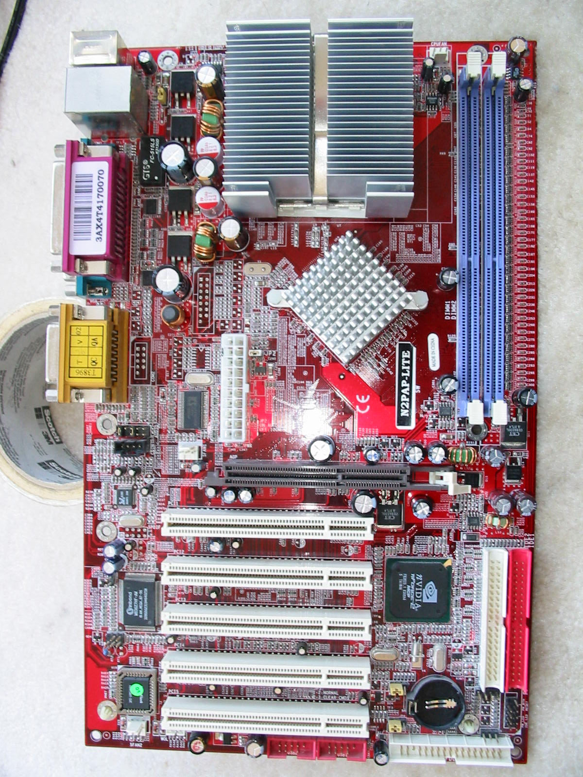
I will start with a good old socket 462 motherboard – a Jetway N2PAP-LITE. If you ask why I post about such an old motherboard now… well, it is because I like fixing / refurbishing old reliable hardware. This board has leaded solder and is from the early 2000’s, when PC components were still designed with some reliability in mind (sans the bad cap brands). The hot red PCB color is also something that can’t be found nowadays – on that note, I really miss the days of colored PCB motherboards.
For those who have not heard the name before, Jetway was one of the many motherboard companies back in the early 2000’s. As with many motherboards of that time, they used obscure capacitor brands. In particular, they always seemed to stick with GSC capacitors (which are probably one of the worst cap brands out there - so bad that they changed names multiple times in hopes of fooling us.)
Nonetheless, I find that Jetway motherboards are usually well-designed, offer good amount of BIOS features, and work great after a recap. It’s unfortunate that they stopped making ATX desktop motherboards around the socket 775 and AM2 era. Jetway still produces motherboards today, but from what I’ve seen, it is mostly (if not all) ITX / mini-ITX form for industrial use and/or POS systems. On the positive side, it seems that they have finally ditched GSC/Evercon/Sacon and use solid polymer capacitors like everyone else.
Anyways, now the more interesting part of the recap: a motherboard diagram with a list of the original capacitors along with what goes where (and other details.)
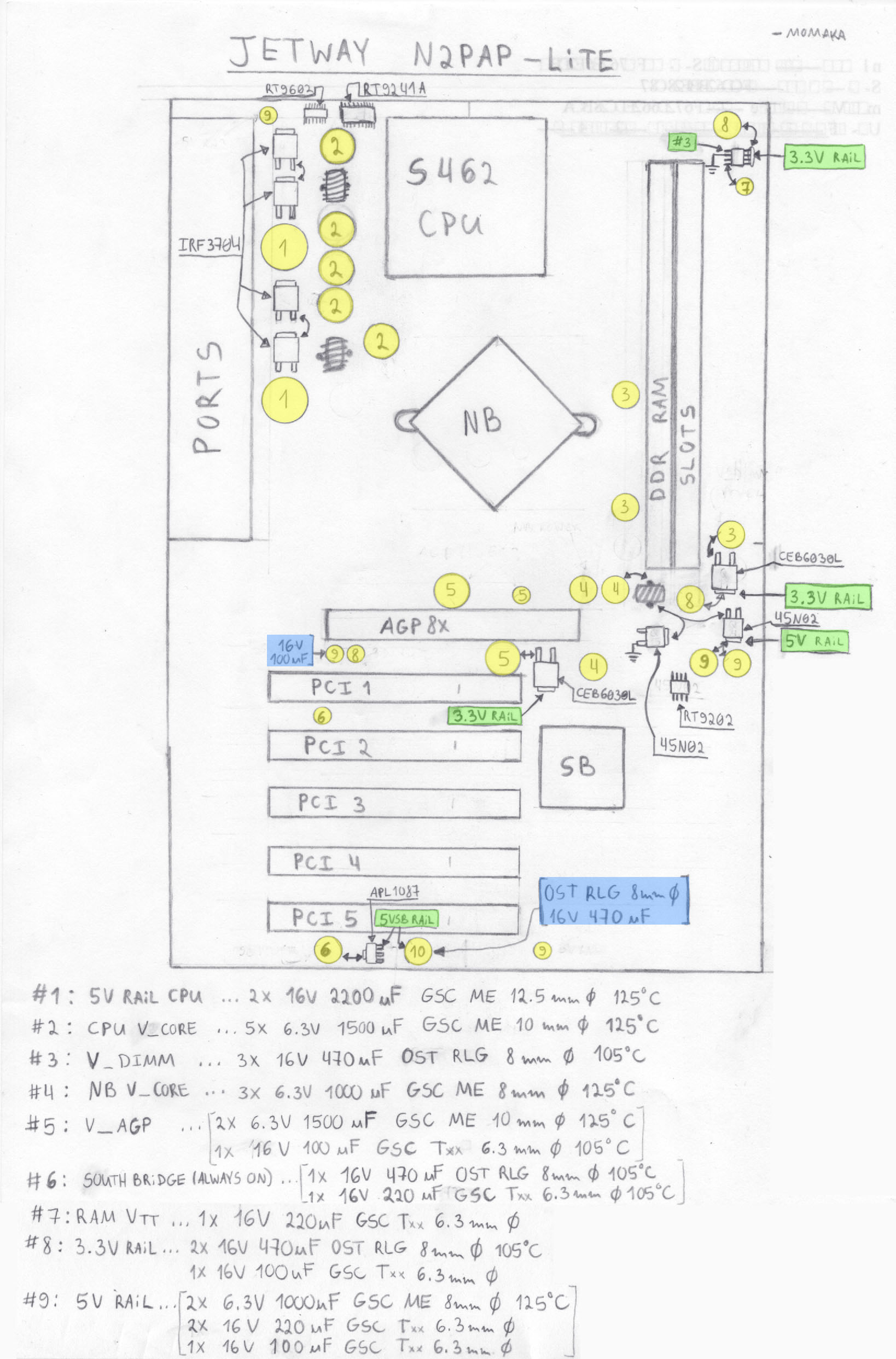
There are important caps on 9 distinct voltage rails, more or less. Going by the cap diagram, these are:
#1: 5 Volt rail for the CPU. (a.k.a. CPU “high” side)
It comes directly out of the 5 V rail on the ATX connector.
- Original caps: 2x GSC ME, 16 V, 2200 uF, 12.5 mm ø, 26 mOhm ESR
- Replaced with: 2x Nichicon HM, 6.3 V, 3300 uF, 12.5 mm ø, 11 mOhm ESR
While it is not advisable to replace caps with ones with a lower voltage rating, I think the diagram clearly shows why I could do that: the Nichicon HM capacitors I used above were on the 5V rail, so there was no need to go with 16V caps at all. Jetway likely used 16V capacitors here to get lower ESR out of less capable parts. The Nichicon HM capacitors I used had lower ESR while also having higher ripple current rating, higher capacitance, and were smaller in size.
Perhaps that goes to show you how “good” GSC ME is . On that note, even Chemicon KZE would have worked here.
#2: CPU Vcore. (a.k.a. CPU “low” side)
This rail provides power to the CPU. It is generated by a 2-phase synchronous buck converter circuit from #1 above..
- Original caps: 5x GSC ME, 6.3 V, 1500 uF, 10 mm ø, 20 mOhm ESR, 2000 mA RC (RC = ripple current)
- Replaced with:
2x Nichicon FPcap R7 series, 6.3 V, 820 uF, 10 mm ø, 7 mOhm ESR, 6100 mA RC
2x Nichicon HZ, 6.3 V, 2200 uF, 10 mm ø, 7 mOhm ESR, 3770 mA RC
Needless to say, this combo of replacement caps was more than adequate for the task. Both the overall capacitance of the CPU Vcore was increased slightly (better for voltage regulation/stability) and the ESR was reduced (better transient response).
Worth noting is that I was actually going to use 6.3 V, 1800 uF Nichicon HM caps instead of the Nichicon HZ caps, but by the time I did the recap, I already had many used/pulled caps from dead Xbox 360 motherboards, so I used those instead. Using Nichicon HZ and polymer caps here was not the least bit necessary , as even the most power-hungry Athlon XP CPUs don’t use more than 80 Watts of power.
#3: V_dimm / V_RAM:
2.5-2.6 Volts for the DDR RAM slots. This rail is generated by MOSFET Q11 (CEB6030L) in a linear fashion.
- Original caps: 3x OST RLG,16 V, 470 uF, 8 mm ø
- Replaced with: 3x Nichicon HD, 10 V, 470 uF, 8 mm ø
Note: this is a linearly-regulated rail, so pretty much any 105°C cap can be used here. Hence why OST RLG worked. But I had the above Nichicon HD in stock, so I used that.
#4: Northbridge V_core/Vcc:
Power for the Northbridge chip, 1.60 Volts. This is another synchronous buck-regulated rail, so ultra-low ESR caps (including polymers) would be okay.
- Original caps: 3x GSC ME, 6.3 V, 1000 uF, 8 mm ø, 35 mOhm ESR, 1129 mA RC
- Replaced with: 3x Nichicon HM, 10 V, 1000 uF, 8 x 15 mm (ø x h)… ESR and RC: way better than GSC ME
#5: V_AGP (AGP bus voltage):
Typically 1.5 V or 0.8 V, but expect anything up to 3.3 V here, due to compatibility with old cards. It is another linearly-regulated rail.
- Original caps:
2x GSC ME, 6.3 V, 1500 uF, 10 mm ø, 35 mOhm ESR, 1129 mA RC
… and a *tiny* GSC T-series 16 V, 100 uF, 6.3 x 11 mm cap for whatever reason
- Replaced with:
2x Nichicon HM, 6.3 V, 1800 uF, 10 mm ø
1x Nichicon HE, 10 V, 220 uF, 6.3 x 11 mm for the tiny GSC cap
#6: Southbridge Vcc (always ON):
3.3 Volt standby rail generated linearly by an ALP1087 LDO from the power supply’s 5VSB rail, and it is always present as long as the PSU is plugged in.
- Original caps:
1x OST RLG, 16 V, 470 uF, 8 mm ø and 1x GSC T-series, 16 V, 220 uF, 6.3 mm ø
- Replaced only the GSC T-series cap with:
1x Nichicon HE, 10 V, 220 uF, 6.3 x 11 mm cap
(I ran out of the 470 uF Nichicon HD caps, but it should be okay, as this is a linearly-regulated rail and does not put caps under any stress. It is possible to get away even with GP caps here, which the OST RLG is.)
#7: RAM Vtt (termination) voltage:
This is typically half of the 2.5/2.6V DDR supply, so expect no more than 1.35 Volts. Another linear rail, generated by U2 (a Winbond W83310S-R) at the upper-right corner of the motherboard. Original cap (yes, ONE cap): GSC T-series 16 V, 220 uF, 6.3x11 mm. Replaced with a Nichicon HE 10 V, 220 uF cap, same 6.3x11 size. Honestly, I expected a bit more filtering from Jetway here, but I suppose that 220 uF cap is enough for two DDR slots.
#8: 3.3 V rail from the PSU:
This supplies various circuits of the board, but most importantly: RAM V_dimm, RAM Vtt, and V_AGP. Had two OST RLG 16 V, 470 uF caps and a single GSC 16 V, 220 uF, 6.3x11 mm cap. Replaced by two United Chemicon KY 10 V, 470 uF caps, 8x12 mm and Nichicon HE 10 V, 220 uF, 6.3x11 mm.
#9: 5 V rail from the PSU:
This supplies various circuits of the board, including the USB, PS/2 ports. But most importantly, it supplies the high side of the buck regulator for the Northbridge V_core/Vcc via caps C402 and C403. Because of that, low ESR caps are recommended for these two spots. This rail has the following caps:
Two GSC ME 6.3 V, 1000 uF, 8 mm diameter.
Two GSC T-series 16 V, 220 uF, 6.3x11 mm caps
One GSC T-series 16 V, 100 uF, 6.3x11 mm cap
I replaced the first two above (C402 and C403) with United Chemicon KZE 10 V, 1000 uF, 8x16 mm. The two 220 uF and one 100 uF GSC caps were all replaced with Nichicon HE 10 V, 220 uF.
#10: 5VSB rail from the PSU:
There is only one cap that filters this rail that should be considered important: It is marked with #10 on the cap map (though, it is not on the list below it). That cap is a 16 V, 470 uF OST RLG. I replaced it with a 10 V, 470 uF United Chemicon KY
Finally, I also replaced the audio output coupling capacitors (C454 and C450). These were standard 100 uF, 16V caps... GSC, of course. I used 2x 220 uF, 16V Panasonic blue GP caps in their place (85°C rated). The increased capacitance of those should help with the low-frequency response of the audio output.
I forgot to take good “before” pictures to show all of the GSC capacitors in their fully glory. Here they are nonetheless:
https://www.badcaps.net/forum/attach...1&d=1498712430
https://www.badcaps.net/forum/attach...1&d=1498712430
I suppose that is not a big loss, though, as none of the GSC caps on my mobo were bulged or leaking. That said, I did test a few on my TT / ESR meter and many of the caps on rail #2 (CPU V_core / low side) as well as #1 (CPU high side) were reading almost abnormally high on capacitance (right around the top of the 20% tolerance). I think only one or two were over 20%. However, they appeared to have good ESR. The high capacitance / good ESR combination often implies high internal leakage in the cap. Although I was able to reform them on my cap reformer, they took longer than a good cap and didn’t hold full charge for too long. So they have started to go high on the leakage current spec, indeed. Oh well, time to put them in my “spare junk caps” bin and in with the new ones. Pictures after the recap:
https://www.badcaps.net/filedata/fetch?id=2200409
https://www.badcaps.net/forum/attach...1&d=1498712430
https://www.badcaps.net/forum/attach...1&d=1498712430
Needless to say, my recap worked just fine. In fact, I took it out today to test some video cards and even just for the sake of powering that PC on. Played some older games too, while at it. It sure brought back some good memories. Oh wait, I forgot about the history of this motherboard / PC. Will be adding in the next post, in case anyone is interested. Stay tuned (or don't, if you have no time for a wall of text again
  )
)
I will start with a good old socket 462 motherboard – a Jetway N2PAP-LITE. If you ask why I post about such an old motherboard now… well, it is because I like fixing / refurbishing old reliable hardware. This board has leaded solder and is from the early 2000’s, when PC components were still designed with some reliability in mind (sans the bad cap brands). The hot red PCB color is also something that can’t be found nowadays – on that note, I really miss the days of colored PCB motherboards.
For those who have not heard the name before, Jetway was one of the many motherboard companies back in the early 2000’s. As with many motherboards of that time, they used obscure capacitor brands. In particular, they always seemed to stick with GSC capacitors (which are probably one of the worst cap brands out there - so bad that they changed names multiple times in hopes of fooling us.)
Nonetheless, I find that Jetway motherboards are usually well-designed, offer good amount of BIOS features, and work great after a recap. It’s unfortunate that they stopped making ATX desktop motherboards around the socket 775 and AM2 era. Jetway still produces motherboards today, but from what I’ve seen, it is mostly (if not all) ITX / mini-ITX form for industrial use and/or POS systems. On the positive side, it seems that they have finally ditched GSC/Evercon/Sacon and use solid polymer capacitors like everyone else.
Anyways, now the more interesting part of the recap: a motherboard diagram with a list of the original capacitors along with what goes where (and other details.)
There are important caps on 9 distinct voltage rails, more or less. Going by the cap diagram, these are:
#1: 5 Volt rail for the CPU. (a.k.a. CPU “high” side)
It comes directly out of the 5 V rail on the ATX connector.
- Original caps: 2x GSC ME, 16 V, 2200 uF, 12.5 mm ø, 26 mOhm ESR
- Replaced with: 2x Nichicon HM, 6.3 V, 3300 uF, 12.5 mm ø, 11 mOhm ESR
While it is not advisable to replace caps with ones with a lower voltage rating, I think the diagram clearly shows why I could do that: the Nichicon HM capacitors I used above were on the 5V rail, so there was no need to go with 16V caps at all. Jetway likely used 16V capacitors here to get lower ESR out of less capable parts. The Nichicon HM capacitors I used had lower ESR while also having higher ripple current rating, higher capacitance, and were smaller in size.
Perhaps that goes to show you how “good” GSC ME is
. On that note, even Chemicon KZE would have worked here. #2: CPU Vcore. (a.k.a. CPU “low” side)
This rail provides power to the CPU. It is generated by a 2-phase synchronous buck converter circuit from #1 above..
- Original caps: 5x GSC ME, 6.3 V, 1500 uF, 10 mm ø, 20 mOhm ESR, 2000 mA RC (RC = ripple current)
- Replaced with:
2x Nichicon FPcap R7 series, 6.3 V, 820 uF, 10 mm ø, 7 mOhm ESR, 6100 mA RC
2x Nichicon HZ, 6.3 V, 2200 uF, 10 mm ø, 7 mOhm ESR, 3770 mA RC
Needless to say, this combo of replacement caps was more than adequate for the task. Both the overall capacitance of the CPU Vcore was increased slightly (better for voltage regulation/stability) and the ESR was reduced (better transient response).
Worth noting is that I was actually going to use 6.3 V, 1800 uF Nichicon HM caps instead of the Nichicon HZ caps, but by the time I did the recap, I already had many used/pulled caps from dead Xbox 360 motherboards, so I used those instead. Using Nichicon HZ and polymer caps here was not the least bit necessary
, as even the most power-hungry Athlon XP CPUs don’t use more than 80 Watts of power.#3: V_dimm / V_RAM:
2.5-2.6 Volts for the DDR RAM slots. This rail is generated by MOSFET Q11 (CEB6030L) in a linear fashion.
- Original caps: 3x OST RLG,16 V, 470 uF, 8 mm ø
- Replaced with: 3x Nichicon HD, 10 V, 470 uF, 8 mm ø
Note: this is a linearly-regulated rail, so pretty much any 105°C cap can be used here. Hence why OST RLG worked. But I had the above Nichicon HD in stock, so I used that.
#4: Northbridge V_core/Vcc:
Power for the Northbridge chip, 1.60 Volts. This is another synchronous buck-regulated rail, so ultra-low ESR caps (including polymers) would be okay.
- Original caps: 3x GSC ME, 6.3 V, 1000 uF, 8 mm ø, 35 mOhm ESR, 1129 mA RC
- Replaced with: 3x Nichicon HM, 10 V, 1000 uF, 8 x 15 mm (ø x h)… ESR and RC: way better than GSC ME
#5: V_AGP (AGP bus voltage):
Typically 1.5 V or 0.8 V, but expect anything up to 3.3 V here, due to compatibility with old cards. It is another linearly-regulated rail.
- Original caps:
2x GSC ME, 6.3 V, 1500 uF, 10 mm ø, 35 mOhm ESR, 1129 mA RC
… and a *tiny* GSC T-series 16 V, 100 uF, 6.3 x 11 mm cap for whatever reason
- Replaced with:
2x Nichicon HM, 6.3 V, 1800 uF, 10 mm ø
1x Nichicon HE, 10 V, 220 uF, 6.3 x 11 mm for the tiny GSC cap
#6: Southbridge Vcc (always ON):
3.3 Volt standby rail generated linearly by an ALP1087 LDO from the power supply’s 5VSB rail, and it is always present as long as the PSU is plugged in.
- Original caps:
1x OST RLG, 16 V, 470 uF, 8 mm ø and 1x GSC T-series, 16 V, 220 uF, 6.3 mm ø
- Replaced only the GSC T-series cap with:
1x Nichicon HE, 10 V, 220 uF, 6.3 x 11 mm cap
(I ran out of the 470 uF Nichicon HD caps, but it should be okay, as this is a linearly-regulated rail and does not put caps under any stress. It is possible to get away even with GP caps here, which the OST RLG is.)
#7: RAM Vtt (termination) voltage:
This is typically half of the 2.5/2.6V DDR supply, so expect no more than 1.35 Volts. Another linear rail, generated by U2 (a Winbond W83310S-R) at the upper-right corner of the motherboard. Original cap (yes, ONE cap): GSC T-series 16 V, 220 uF, 6.3x11 mm. Replaced with a Nichicon HE 10 V, 220 uF cap, same 6.3x11 size. Honestly, I expected a bit more filtering from Jetway here, but I suppose that 220 uF cap is enough for two DDR slots.
#8: 3.3 V rail from the PSU:
This supplies various circuits of the board, but most importantly: RAM V_dimm, RAM Vtt, and V_AGP. Had two OST RLG 16 V, 470 uF caps and a single GSC 16 V, 220 uF, 6.3x11 mm cap. Replaced by two United Chemicon KY 10 V, 470 uF caps, 8x12 mm and Nichicon HE 10 V, 220 uF, 6.3x11 mm.
#9: 5 V rail from the PSU:
This supplies various circuits of the board, including the USB, PS/2 ports. But most importantly, it supplies the high side of the buck regulator for the Northbridge V_core/Vcc via caps C402 and C403. Because of that, low ESR caps are recommended for these two spots. This rail has the following caps:
Two GSC ME 6.3 V, 1000 uF, 8 mm diameter.
Two GSC T-series 16 V, 220 uF, 6.3x11 mm caps
One GSC T-series 16 V, 100 uF, 6.3x11 mm cap
I replaced the first two above (C402 and C403) with United Chemicon KZE 10 V, 1000 uF, 8x16 mm. The two 220 uF and one 100 uF GSC caps were all replaced with Nichicon HE 10 V, 220 uF.
#10: 5VSB rail from the PSU:
There is only one cap that filters this rail that should be considered important: It is marked with #10 on the cap map (though, it is not on the list below it). That cap is a 16 V, 470 uF OST RLG. I replaced it with a 10 V, 470 uF United Chemicon KY
Finally, I also replaced the audio output coupling capacitors (C454 and C450). These were standard 100 uF, 16V caps... GSC, of course. I used 2x 220 uF, 16V Panasonic blue GP caps in their place (85°C rated). The increased capacitance of those should help with the low-frequency response of the audio output.
I forgot to take good “before” pictures to show all of the GSC capacitors in their fully glory. Here they are nonetheless:
https://www.badcaps.net/forum/attach...1&d=1498712430
https://www.badcaps.net/forum/attach...1&d=1498712430
I suppose that is not a big loss, though, as none of the GSC caps on my mobo were bulged or leaking. That said, I did test a few on my TT / ESR meter and many of the caps on rail #2 (CPU V_core / low side) as well as #1 (CPU high side) were reading almost abnormally high on capacitance (right around the top of the 20% tolerance). I think only one or two were over 20%. However, they appeared to have good ESR. The high capacitance / good ESR combination often implies high internal leakage in the cap. Although I was able to reform them on my cap reformer, they took longer than a good cap and didn’t hold full charge for too long. So they have started to go high on the leakage current spec, indeed. Oh well, time to put them in my “spare junk caps” bin and in with the new ones. Pictures after the recap:
https://www.badcaps.net/filedata/fetch?id=2200409
https://www.badcaps.net/forum/attach...1&d=1498712430
https://www.badcaps.net/forum/attach...1&d=1498712430
Needless to say, my recap worked just fine. In fact, I took it out today to test some video cards and even just for the sake of powering that PC on. Played some older games too, while at it. It sure brought back some good memories.
Oh wait, I forgot about the history of this motherboard / PC. Will be adding in the next post, in case anyone is interested. Stay tuned (or don't, if you have no time for a wall of text again
Attached Files
")
 , and a 20 GB Maxtor HDD…yes, a far cry from a proper gaming PC for that era
  ), and I have to say, WHAT A FREAKIN’ IMPROVEMENT! (sans the 9800 XL artifacting in some games)


 I don't think those GP GSC series actually have any series designation. IIRC, "T" seems to be part of a factory / date code. Those linear regulated rails do not stress the capacitors after so long as the regulators themselves aren't dissipating too much heat, thus radiating too much heat toward the capacitors next to them.


Comment