And for today's “Other Weird Devices” thread, let's have a look at an Aquarius WaterPik WP-100W water flosser. What is it? Apparently, it's kind of a power washer, of sorts, for cleaning teeth & gums. Who knew these existed, right? 
A family friend asked me to take a look at their older one, since it stopped powering On. So let's have a look at what went wrong.
First, a view of the box (note: it's from a newer model) and the device itself:
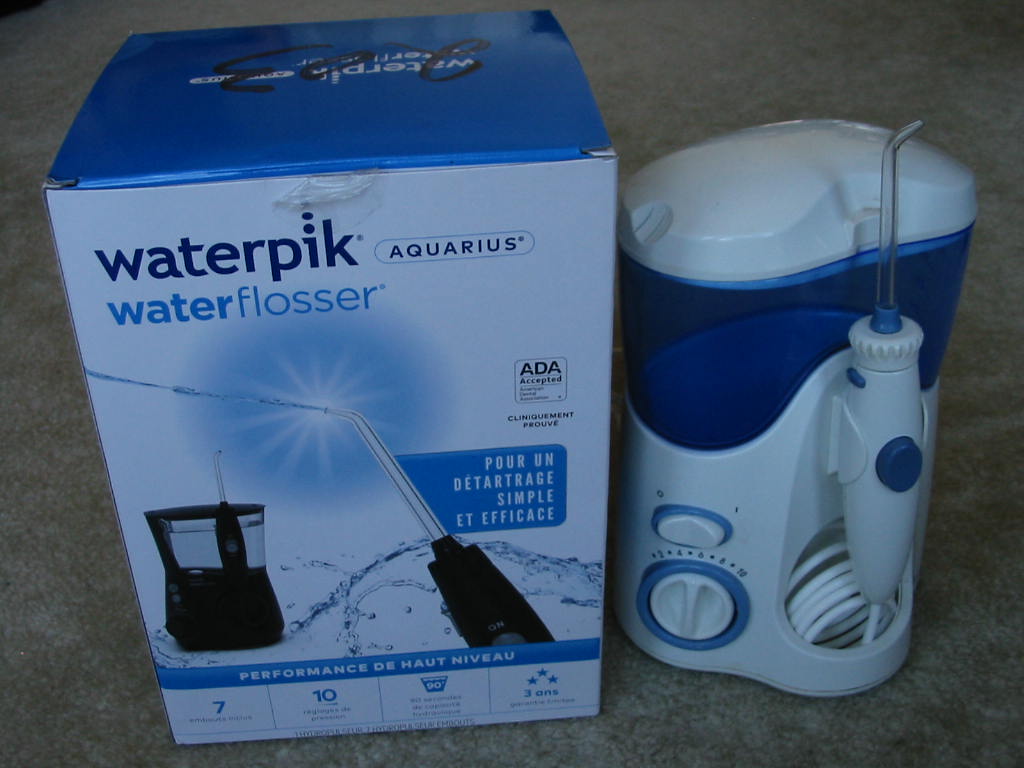
^ Is it me, or does anyone else find it a little humorous how the box says it's “ADA Accepted”? I'm not here to try to sink the reputation of this product… buy to me at least, the wording makes it sound as if this device probably doesn't have many benefits for your teeth/gums (or at least not any more than regular toothbrush, despite the box claiming otherwise.) On the other hand, it also probably doesn't hurt anything in any way… hence the “Accepted” instead of “Approved” label. But anyways, let's move on…
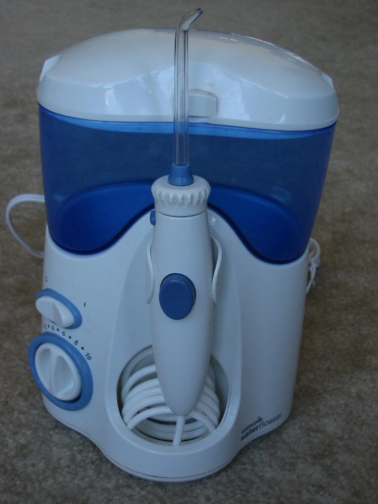
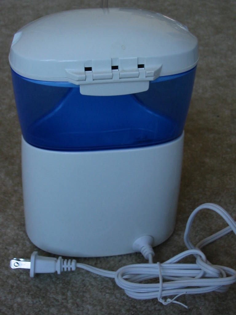
A few pictures of the device itself:
Label with model number info:
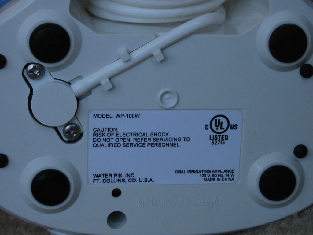
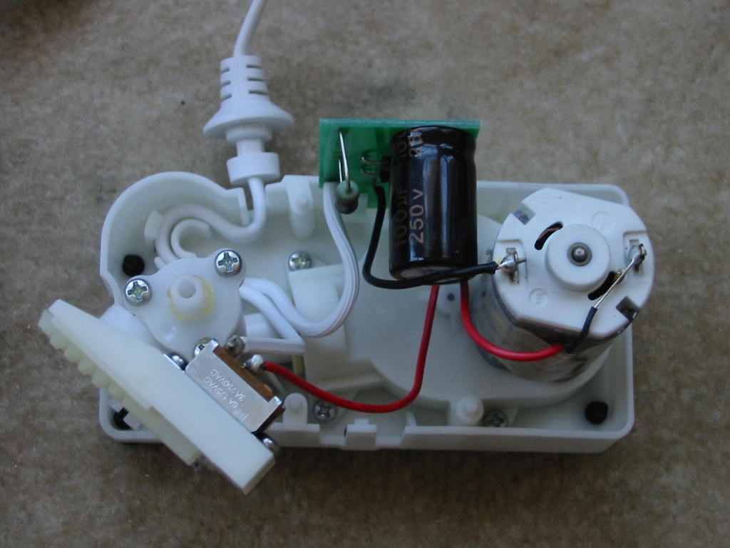
Now for the fun part: tare it open. OK, I didn't quite “tear” it. Instead, all that is needed here is to remove 2 screws holding the “pressure hose” and then 4 more screws from the bottom of the case. However, this still won't allow the bottom cover to come off. Once all of the screws are removed, pulling force has to be asserted onto the bottom cover, after which there are 4 small rubber feet that need to be pushed in with a small screwdriver to separate the pump base assembly from the bottom cover. The result is this:
Bottom cover:
With the bottom cover off, next step is to take out the pump base assembly and electronics from the top case. To do that, the water flow knob needs to be removed by prying it from the shaft from inside the case. Once that is off, everything should come apart easily.
Top case/cover:
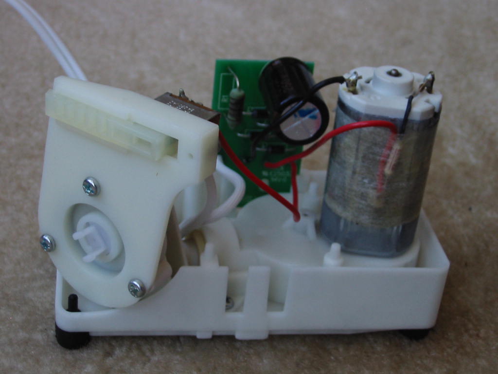
Pump base + electronics:
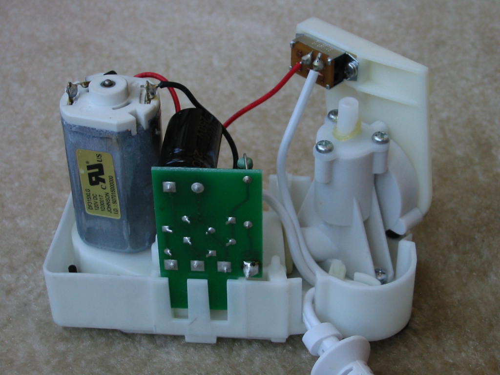
Motor info: it's a Johnson Electric, model DF315XLG, rated for 120V DC.
^ It's good to see a quality brand motor used here… though, for the $80-100 that these flosser devices cost, I think that leaves a little more to be desired for the quality of the rest of the device. The pump and gears, for example, are all plastic.
Moving onto the circuit board - there's not much to it: four diodes for a full-bridge rectifier, an electrolytic cap for filtering the rectified DC, and a fusible MOX resistor in series with the Neutral line. Live is connected to a 3 Amp, 125VAC switch before going into the circuit board.
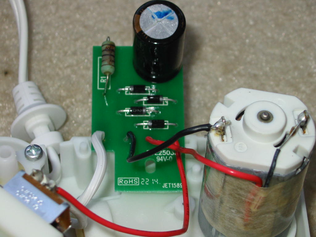
The 4 diodes are regular 1N4004 silicon parts (1 Amp, 400V) and the MOX resistor measures around 47 Ohms (actual reading: 48.5 Ohms.) I think it's rated for either 1 or 2 Watts. I couldn't figure out the rated resistance from the color bands due to burn-in on the coating. It looks like the resistor was pushed a bit too hard.
Since this is BCN, below is an image of the electrolytic cap.
In case the picture isn't clear… brand is “KOME” (series: “TY”) and the cap is rated for 250V, 100 uF, and 105°C. I didn't bother looking up a datasheet for it, as it's probably cheap Chinese GP stuff. But for filtering rectified line DC, it probably doesn't matter too much.
And finally, here's why the device wasn't working:
TCO (thermal cutout) was open. It's a Panasonic/Matsushita EYP2BN109. Not sure if it had operated before (and how many times.) But having a rated functioning temperature of up to 114°C, I think it would have been visible if anything (including the TCO itself) ran that hot. So I'm not sure what caused it to fail (perhaps improper soldering temperature, or perhaps just not adequate enough to handle the power requirements of this device?) I checked the power draw of the flosser by temporarily jumping across the TCO with a piece of wire, and the flosser didn't draw more than 15 Watts on my K-A-W meter while operating. So the rating on the label is accurate, which means the running current isn't high. And on that note, the motor didn't get too warm either for the 1 minute or so I had it running while emptying a full tank of water. The only thing that seemed to run hot was the R1 resistor. In fact, that yellowing of the plastic seen on the top case/cover is right where R1 is. Doing some basic calculations… with 120V AC and 15 Watts of power draw, the flosser should be drawing about 0.125 Amps from the wall. By I^2R losses, that makes R1 dissipation around 0.75 Watts… which seems about right to make it run hot if it's rated for 1 or 2 Watts (I'm guessing probably 1 Watt.)
So it looks like the TCO is really the only part that went bad here. Everything else seems to be functioning OK. I wonder if I should find a different TCO replacement, though (well, I will have to, as the EYP series TCOs from Matsushita/Panasonic are discontinued now.) And on that note, I wonder why they have the TCO right on the motor. Is this the part that is expected to run the hottest if the device is left On for an extended period of time? Granted that's where all the power is going into the device, it makes sense, I suppose. But then why use a TCO rated for 114°C? Shouldn't the rating be a little lower? I feel the plastic base holding the motor would melt if anything got that hot. Moreover, I don't like the fact that the TCO is held onto the motor with just tape and that there is only 1 layer of tape insulation, separating one lead of the TCO (that carries positive rectified DC voltage) from the motor's case.
At high temperature, they really are counting on the tape to not melt here (unless the tape is special… though it doesn't look like it.) Even so, I feel a bit uneasy here about the electrical insulation, despite the UL certification.
On a related note, I wonder if R1 will/should burn out first before the TCO, seeing how hot it seems to have been running. Also, I don't see a fuse anywhere. I know R1 should act as one in the event the “bridge rectifier” goes bad or the electrolytic cap goes shorted… but is that good practice? R1 is on the Neutral, and there is nothing to disconnect the Live in case of failure. So perhaps it would be a good idea to add a series fuse to the Live while at it? (1 Amp, 250V??)
Lastly, a warning to anyone trying to service one of these flossers: if the TCO goes bad (open), like in my case, this can leave the electrolytic cap fully charged to ~160V DC. What's worse is that there is conformal coating on the PCB. So when I went to check if the cap was charged before touching anything in there, I was mislead to believe that it wad discharged due to not getting any reading on my multimeter simply due to the multimeter's leads not being able to make good contact with the solder on the PCB from the conformal coating. It wasn't until I accidentally touched both the (+) lead on the motor and the cap's case (vent) that I felt slight “tingles”, realizing something wasn't quite right. Luckily (or not? ) this happened before I tried testing the diodes with my multimeter. I imagine a cheap meter could easily get zapped by the energy stored in the cap… or worse, if you happen to run that potential across your body. So do beware that this could be a shock hazard if the TCO is open. There is no discharge resistor across the cap.
Anyways… off to finding a replacement TCO now, I suppose.
A family friend asked me to take a look at their older one, since it stopped powering On. So let's have a look at what went wrong.
First, a view of the box (note: it's from a newer model) and the device itself:
^ Is it me, or does anyone else find it a little humorous how the box says it's “ADA Accepted”?
I'm not here to try to sink the reputation of this product… buy to me at least, the wording makes it sound as if this device probably doesn't have many benefits for your teeth/gums (or at least not any more than regular toothbrush, despite the box claiming otherwise.) On the other hand, it also probably doesn't hurt anything in any way… hence the “Accepted” instead of “Approved” label. But anyways, let's move on…A few pictures of the device itself:
Label with model number info:
Now for the fun part: tare it open. OK, I didn't quite “tear” it.
Instead, all that is needed here is to remove 2 screws holding the “pressure hose” and then 4 more screws from the bottom of the case. However, this still won't allow the bottom cover to come off. Once all of the screws are removed, pulling force has to be asserted onto the bottom cover, after which there are 4 small rubber feet that need to be pushed in with a small screwdriver to separate the pump base assembly from the bottom cover. The result is this:Bottom cover:
With the bottom cover off, next step is to take out the pump base assembly and electronics from the top case. To do that, the water flow knob needs to be removed by prying it from the shaft from inside the case. Once that is off, everything should come apart easily.
Top case/cover:
Pump base + electronics:
Motor info: it's a Johnson Electric, model DF315XLG, rated for 120V DC.
^ It's good to see a quality brand motor used here… though, for the $80-100 that these flosser devices cost,
I think that leaves a little more to be desired for the quality of the rest of the device. The pump and gears, for example, are all plastic.Moving onto the circuit board - there's not much to it: four diodes for a full-bridge rectifier, an electrolytic cap for filtering the rectified DC, and a fusible MOX resistor in series with the Neutral line. Live is connected to a 3 Amp, 125VAC switch before going into the circuit board.
The 4 diodes are regular 1N4004 silicon parts (1 Amp, 400V) and the MOX resistor measures around 47 Ohms (actual reading: 48.5 Ohms.) I think it's rated for either 1 or 2 Watts. I couldn't figure out the rated resistance from the color bands due to burn-in on the coating. It looks like the resistor was pushed a bit too hard.
Since this is BCN, below is an image of the electrolytic cap.
In case the picture isn't clear… brand is “KOME” (series: “TY”) and the cap is rated for 250V, 100 uF, and 105°C. I didn't bother looking up a datasheet for it, as it's probably cheap Chinese GP stuff. But for filtering rectified line DC, it probably doesn't matter too much.
And finally, here's why the device wasn't working:
TCO (thermal cutout) was open. It's a Panasonic/Matsushita EYP2BN109. Not sure if it had operated before (and how many times.) But having a rated functioning temperature of up to 114°C, I think it would have been visible if anything (including the TCO itself) ran that hot. So I'm not sure what caused it to fail (perhaps improper soldering temperature, or perhaps just not adequate enough to handle the power requirements of this device?) I checked the power draw of the flosser by temporarily jumping across the TCO with a piece of wire, and the flosser didn't draw more than 15 Watts on my K-A-W meter while operating. So the rating on the label is accurate, which means the running current isn't high. And on that note, the motor didn't get too warm either for the 1 minute or so I had it running while emptying a full tank of water. The only thing that seemed to run hot was the R1 resistor. In fact, that yellowing of the plastic seen on the top case/cover is right where R1 is. Doing some basic calculations… with 120V AC and 15 Watts of power draw, the flosser should be drawing about 0.125 Amps from the wall. By I^2R losses, that makes R1 dissipation around 0.75 Watts… which seems about right to make it run hot if it's rated for 1 or 2 Watts (I'm guessing probably 1 Watt.)
So it looks like the TCO is really the only part that went bad here. Everything else seems to be functioning OK. I wonder if I should find a different TCO replacement, though (well, I will have to, as the EYP series TCOs from Matsushita/Panasonic are discontinued now.) And on that note, I wonder why they have the TCO right on the motor. Is this the part that is expected to run the hottest if the device is left On for an extended period of time? Granted that's where all the power is going into the device, it makes sense, I suppose. But then why use a TCO rated for 114°C? Shouldn't the rating be a little lower? I feel the plastic base holding the motor would melt if anything got that hot. Moreover, I don't like the fact that the TCO is held onto the motor with just tape and that there is only 1 layer of tape insulation, separating one lead of the TCO (that carries positive rectified DC voltage) from the motor's case.
At high temperature, they really are counting on the tape to not melt here (unless the tape is special… though it doesn't look like it.) Even so, I feel a bit uneasy here about the electrical insulation, despite the UL certification.
On a related note, I wonder if R1 will/should burn out first before the TCO, seeing how hot it seems to have been running. Also, I don't see a fuse anywhere. I know R1 should act as one in the event the “bridge rectifier” goes bad or the electrolytic cap goes shorted… but is that good practice? R1 is on the Neutral, and there is nothing to disconnect the Live in case of failure. So perhaps it would be a good idea to add a series fuse to the Live while at it? (1 Amp, 250V??)
Lastly, a warning to anyone trying to service one of these flossers: if the TCO goes bad (open), like in my case, this can leave the electrolytic cap fully charged to ~160V DC. What's worse is that there is conformal coating on the PCB. So when I went to check if the cap was charged before touching anything in there, I was mislead to believe that it wad discharged due to not getting any reading on my multimeter simply due to the multimeter's leads not being able to make good contact with the solder on the PCB from the conformal coating. It wasn't until I accidentally touched both the (+) lead on the motor and the cap's case (vent) that I felt slight “tingles”, realizing something wasn't quite right. Luckily (or not?
) this happened before I tried testing the diodes with my multimeter. I imagine a cheap meter could easily get zapped by the energy stored in the cap… or worse, if you happen to run that potential across your body. So do beware that this could be a shock hazard if the TCO is open. There is no discharge resistor across the cap.Anyways… off to finding a replacement TCO now, I suppose.
Attached Files
if you find these attachements useful please consider making a small donation to the site


Comment