Announcement

Collapse
No announcement yet.

Dell 5590 LA-F412P does charge with USB-C not with DC-Jack

Collapse
X
 
  • Filter
  • Time
  • Show
Clear All
new posts

    Dell 5590 LA-F412P does charge with USB-C not with DC-Jack

    As mentioned, I have a Dell 5590 laptop with motherboard LA-F412P.
    This laptop works with the USB-C charger and not with DC-Jack charger.
    With the USB-C charger attached, the battery is charging and in the BIOS the charger is also recognized.

    With the DC-Jack charger attached (USB-C charger removed), the light of the charger is not going off and the BIOS does not see the charger (message AC Adapter = Not installed). I'm using original Dell chargers and I have tested the used chargers on other Dell laptops and they are working correctly.
    I have replaced the DC-Jack, but still the same.

    According to owner of this laptop, they have used a wrong charger (don't know any other information, cannot ask the owner (holidays)).

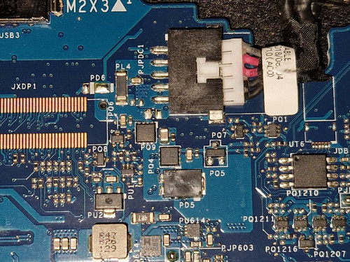
    Have done some measurements and the first mosfet PQ9, there is on the Source 19.5V and the Gate has 17.8V, there is no voltage on the Drain.
    Done some random measurements, and did not find any shorts on the board.
    When I bridge the Source and Drain with a wire, the laptop turns on and is working correctly. In the BIOS the message "AC Adapter = Not installed" is then still there.


    According to my knowledge, when there are issues with the NB_PSID signal, the laptop should turn on, but the battery does not charge and the wattage cannot be determined.


    Any suggestions or directions ?

    #2
    Link the schematics if available but do not post them here directly. The schematics should be in the dedicated forum.

    Update : Could not find the schematic in my paid sub. You will have to locate the charger IC on your board to continue with the investigation. Probably will be a TI / BQ series charger IC which will feature the ACDRV pin to drive the 2 x DCin mosfets using ~25v on the gate pins to enable each.

    What are the topside markings of your charger IC?
    Last edited by mon2; 12-29-2023, 03:03 PM.

    Comment


      #3
      Just stick to basics and problem can be solved.

      01.Check dc-in fets in resistance mode between
      Source-Gate
      Source-Drain
      Gate-Drain

      Check PS_ID circuit. There are plenty of threads on this issue.

      Comment


        #4
        Originally posted by mon2 View Post
        Link the schematics if available but do not post them here directly. The schematics should be in the dedicated forum.

        Update : Could not find the schematic in my paid sub. You will have to locate the charger IC on your board to continue with the investigation. Probably will be a TI / BQ series charger IC which will feature the ACDRV pin to drive the 2 x DCin mosfets using ~25v on the gate pins to enable each.

        What are the topside markings of your charger IC?
        I have searched on the board for a TI / BQ chip, did not find it. I have the schematic of a Dell 5580 board la-e151p. Those 5580 board are visual very identical as the 5590 boards.


        Originally posted by mcplslg123 View Post
        Just stick to basics and problem can be solved.

        01.Check dc-in fets in resistance mode between
        Source-Gate
        Source-Drain
        Gate-Drain

        Check PS_ID circuit. There are plenty of threads on this issue.
        PQ9
        Source-Gate 1001K
        Source-Drain 177K
        Gate-Drain 1174K

        PQ4
        Source-Gate 496K
        Source-Drain 103K
        Gate-Drain 661K

        Regarding the PS_ID circuit, with a not working PS_ID circuit, shouldn't the board start ?

        Comment


          #5
          PQ9
          Source-Drain 177K

          PQ4
          Source-Drain 103K
          These are low readings for a mosfet. At least one is defective. Carefully flux and remove one of the mosfets (suggest the 2nd one on the board) -> allow it to cool and then measure it again when it is on your work table. Before starting, protect the nearby plastic parts from the heat. You can consider to use aluminum foil, etc. + low air pressure. Once the mosfet is removed, check the other mosfet's resistance again. It too may be defective. There are many replacement parts that can work to replace these devices.

          Post the topside markings of these mosfets for guidance.

          Comment


            #6
            Measurement of the mosfets.

            PQ9 ZB0803 pdf
            Source-Gate no measurement
            Source-Drain resistance 1860K and goes higher it seems, my multi meter cannot show that.
            Gate-Drain no measurement

            PQ4 7409 pdf
            Source-Gate no measurement
            Source-Drain no measurement
            Gate-Drain no measurement


            I have done the same measurements, but then on the PCB and the place of those mosfets
            PQ9
            Source-Gate 1002K
            Source-Drain 170K
            Gate-Drain 1174K

            PQ4 7409
            Source-Gate 496K
            Source-Drain 165K
            Gate-Drain 648K

            Comment

            Working...
            X