Did you make sure the replacement mainboard was a match, usually done by matching numbers on a sticker on the boards and did you try a firmware update on the new board, also not always but in some cases a lightning strike can mess up the firmware and an update can fix it.
-
-
Can you test these 2 diodes correctly, meter in diode mode, tv unplugged from power, look at this video it's very simple to test them, he's checking a double diode around 7:40 mark: https://www.youtube.com/watch?v=0VfSvU1AHfcOriginally posted by karthur View PostLast edited by nomoresonys; 07-16-2024, 06:30 AM.Quit due to disrespect from unpaid sta,ff.
Comment
-
I checked the "new" board the best I could (it doesn't have the stickers on it). From the ad where I bought it, it should be the same as my OEM board. I have not done a firmware update. Not even sure how to do that without being able to get to the MENU screen. Any information on how to accomplish that would be welcomed.Originally posted by nomoresonys View Post
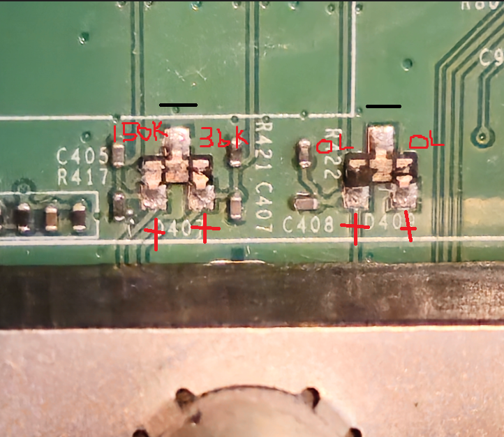
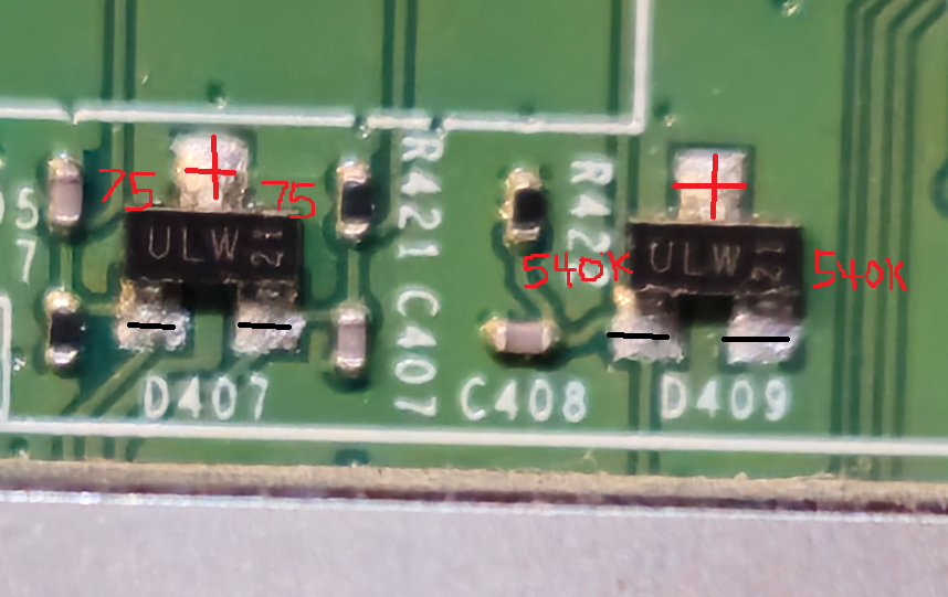
I tested both the original OEM board and the replacement board. These chips were damaged on my original board as you can see from these pictures.Can you test these 2 diodes correctly, meter in diode mode, tv unplugged from power, look at this video it's very simple to test them,
The original OEM (damaged) board.

New Replacement Board

ThanksLast edited by karthur; 07-16-2024, 05:35 PM.Comment
-
Take the original main board, remove D407, D409 and test the tv, power board is almost surely ok, but you have not tested the power on-off pin.. further ic905 you have posted only one voltage, pins are 3!!Comment
-
Again you're showing ohm readings, PUT meter in DIODE mode and check per the video.Originally posted by karthur View PostQuit due to disrespect from unpaid sta,ff.Comment
-
Going to give it my best guess, tho I don't like guessing. Some possibilities, may have bought a bad mainboard or damaged in transit or mis-handled, mainboard may not be a match, can you show good focused picture of both boards, WHOLE board not just the damaged part.Last edited by nomoresonys; 07-17-2024, 05:52 AM.Quit due to disrespect from unpaid sta,ff.Comment
-
Comment
-
My apology for checking those wrong. Here is the readings I am getting with the meter in DIODE mode.Originally posted by nomoresonys View Post
Attached FilesComment
-
-
Here is a picture of the "New" board.
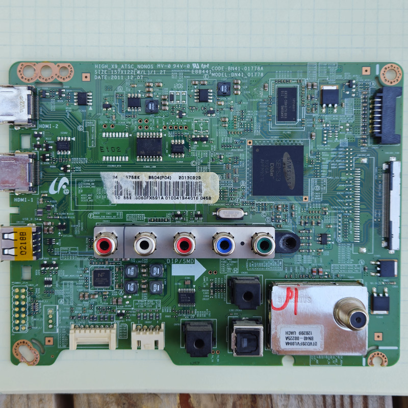 Attached Files
Comment
-
-
This is a picture of my original board. I have removed the IC901. I was trying to get a dump from it. I could read it, but was not certain I had a good file..
 Attached FilesLast edited by karthur; 07-17-2024, 05:16 PM.
Comment
-
-
I checked the power on-off and got 5.0 Volts. See post #9 on first page. For the IC905, here is the readings I get on my replacement board. If I checked this wrong, just let me know how I should be checking it.Originally posted by Davi.p View Post
Thanks
Comment
-
If it was me, I would try another mainboard, sometimes you get a bad one, you should be able to get a refund.Quit due to disrespect from unpaid sta,ff.Comment
-
both things wrong.. in the early posts you tested only odd pins, pins are in 2 rows, you wrote the signals marking as them are one only thing but are 2 signals in a row, power on-off is one thing, A5v is another and you are measuring A5v only..
second thing, i want you to bear with original board for now, checking ic905 i mean the pins voltages respect to GND, i guess this is a voltage reg. but not sure, tell eventually its code..Comment
-
I have asked for a refund and I am ordering another replacement. What do you think about the readings I got on D407 and D409 (post #48 above)? It appears to me that D407 on the new board is no good because it should be ZERO with "+" on the cathode.Originally posted by nomoresonys View Post
Comment
-
Davi,Originally posted by Davi.p View Post
Here are the readings for all 14 pins from the power board. These readings are between ground and the pin with power on the board. For reference, I also show the pin map print on the board. The pins that I see are out of range are Pins 2 and 14. I am not sure what Vamp is, so 5 and 6 might also be out of range.
For the IC905, I have remove the IC901 but here are the IC901 volt readings.
Comment
-
Now is 100% clear, so the power board is ok, all readings are within specs, Vamp is Audio amplifier voltage and is ok at 13v, the ic905 is wrong if is a voltage reg. , tell me the marking code, it has input 5 - O volt but output must be 3,3v i guess..Comment
-
To me it looks like both diodes on old board are bad, 409 gives nothing, 407 only shows one diode, 407 on the new board seems strange since it gives a reading in both directions, which it should NOT.Originally posted by karthur View PostQuit due to disrespect from unpaid sta,ff.Comment
-
Comment
-
i have already seen, the best site for smd codes is down now..Comment
-
No i can't find it, i remember i have seen it..Comment
Comment