Announcement

Collapse
No announcement yet.

Grundig Vision 9 37 9880 T USB (Chassis SR) TV Repair Help - Distorted Subwoofer Sound and overall weird sound waveforms

Collapse
X
 
  • Filter
  • Time
  • Show
Clear All
new posts

    Grundig Vision 9 37 9880 T USB (Chassis SR) TV Repair Help - Distorted Subwoofer Sound and overall weird sound waveforms

    Good day ladies and gentleman!

    I am currently trying to repair a Grundig Vision 9 37 9880 T USB LCD TV for a friend that has a weird audio problem. Basically everything works fine except for the heavily distorted sound when the Subwoofer module is connected and there is a buzzing sound coming from the PSU PCB.

    This seems to be a rather rare TV so there is not much prior on topic help to be found however a service manual is available at the usual sources (Electro Tanya i.e.).

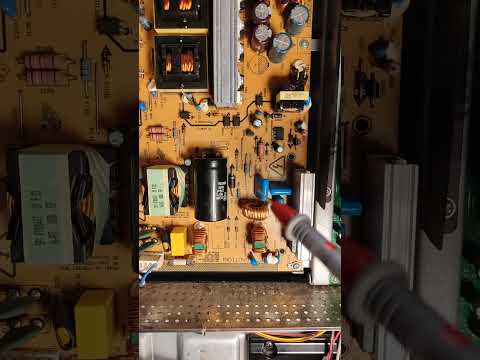
    I think the PSU buzzing comes from one of the coils near the bridge rectifier but I am not sure if this really is a problem or just a very noisy power supply. I do have professional experience with electronics but I am certainly not a TV repair guy. The output DC voltages from the PSU PCB seem to be fine. So while annoying for the moment I think this might just be severe coil whine and the issue lies with the sound chip or main logic board.

    The audio system seems to be divided into a sound bar (sound projector) that's mounted beneath the screen and a subwoofer module that is mounted to the back shell / housing of the TV.

    When the TV is turned on after being turned off at the power strip level a farting like noise is emitted from the sub module but that goes away shortly after.

    https://www.youtube.com/watch?v=eqRuUCotLAI

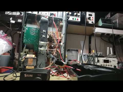
    My approach to test the audio was to listen to some music which sound distorted as if the sub speakers are damaged however I testes the subwoofer module on the bench with an external amplifier and the speakers seem to be fine. No damage to the rubber surrounds and tone is fine. No scratching. Coils seem to be able to move freely.

    The next thing I tried was to feed a 20Hz to 20Khz sine sweep (found on youtube) to the system via HDMI3 and it sounds horrible. More like clicking or rattling in the lower frequencies. When the frequency gets higher the sound is more normal for a sine signal.

    I also measure total garbage signals even with a steady 1kHz sine wave on all terminals (headphone out, subwoofer speaker terminals, tweeter speaker terminals) with my new Rigol DHO804 scope.

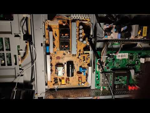
    Measurements with DMM on the PSU PCB's connector to the logic board:


    +5VS, 5.214V
    GND, 0.01V
    BL, 3.265V
    DIM, 3.290V
    +24V, 23.96V
    STBY, 2.946V
    +12V, 11.899V
    GND, 0.0214V

    Measurements with DMM on the PSU PCB's connector to the backlight inverter board:


    GND, -0.0042V
    +24V, 23.95V
    BL, 3.265V
    DIM, no wire connected

    Some Videos that I've shot with some scope measurements down below.

    Grundig 37 9880 T USB PSU Buzzing Noise


    Grundig 37 9880 T USB Farting Noise
    https://www.youtube.com/watch?v=eqRuUCotLAI

    Grundig 37 9880 T USB 100Hz Sine Garbage at the Headphone Out
    https://www.youtube.com/watch?v=5PlE8wRZYbk

    Grundig 37 9880 T USB 100Hz Sine Measured (at Sub Module)
    https://www.youtube.com/watch?v=_xRJSTvvYiE

    Grundig 37 9880 T USB Thermal 1
    https://www.youtube.com/watch?v=QBh1jmPa3t8

    Grundig 37 9880 T USB Thermal 2
    https://www.youtube.com/watch?v=e62o-2_bwEA


    I suspect that the STV8357FSX sound processor is damaged but I don't know if this could also be some other issue related to the PSU buzzing. Help is much appreciated.
    Last edited by LEECH666; 01-20-2024, 06:45 PM.

    #2
    Some scope screenshots attached ...
    Attached Files
    Last edited by LEECH666; 01-19-2024, 06:23 PM.

    Comment


      #3
      Buzzing Noise at PSU could be Filter leak.... or Overload to narrow the issue. run the PSU in stand alone test.. if the Buzzing Noise disappear... then the issue not at PSU

      Comment


        #4
        Hi Diah, thanks for your reply. I have to admit that I don't know too much about TV PSUs. I read in the basic TV repair guide that the TV PSU waits for an "ok turn on"-Signal from the logic board. I assume this is the STBY labled pin on the connector that goes to the logic board but how do I get it to power up when the logic board is not connected? The STBY pin measures around 2.9V during operation when everything is connected ... so do I just apply 2.9V to that pin via an externally connected lab supply to turn it on?

        Comment


          #5
          Originally posted by LEECH666 View Post
          Hi Diah, thanks for your reply. I have to admit that I don't know too much about TV PSUs. I read in the basic TV repair guide that the TV PSU waits for an "ok turn on"-Signal from the logic board. I assume this is the STBY labled pin on the connector that goes to the logic board but how do I get it to power up when the logic board is not connected? The STBY pin measures around 2.9V during operation when everything is connected ... so do I just apply 2.9V to that pin via an externally connected lab supply to turn it on?
          PSU with out Main boards can run as stand alone... disconnect the MB from the PSU socket.. plug in wall messure yours socket you will have only one V STB usually 3-.3V -5V. in yours case i think its 5VS will be... connect via 1KR to in yours case STBY ... and to too BL ( which i think it BL_ON and Dimm... yours PSU will start and power up the BL and you will have on the socket 12V pin & +24V ( this for sound )

          you need to chevk first just plug in wall and the V which exsist will be PSU stand buy V. and the other Pins will be Power_ON ( this will switch 12V & 24V )

          Comment


            #6
            +5VS seems to be too be the standby supply voltage as it is the only voltage being present after the TV is switched to standby via the remote.

            So if I understood you correctly I should connect the +5VS pin via a 1K resistor to the STBY and BL pin like shown in the attachment?
            Attached Files
            Last edited by LEECH666; 01-20-2024, 08:48 AM.

            Comment


              #7
              so yours PSU Socket i will rename the pins to be more understandable
              5VS = STBY .. STB= Power _ON BL = BL_ON DIM=DIM for BL
              so STBY via 1KR connected to Power_ON & BL_ON ... if the BL didnt power on... you need to add DIM to the same rail of the 1KR.
              PSU will start On. and you will have 12 & 24V... if the buzzing remain... disconnect the BL socket from PSU and check.the noise..
              if PSU & BL power up and No buzzing... keep this mode test... disconnect the LVDS between the MB and T-CON if you have external T-CON.... take from the socket of PSU 12V line and fed the T-CON Fuse F1... check the buzzing... if no more buzzing mean the issue at MB.. i so we do narrow the issue to be sure which part make the overload on PSU

              Comment


                #8
                Thank you again for your help so far. Your short hand style of writing is a bit hard for me to decypher. I assume when you say "if the BL didnt power on" you mean "if the back light (24V to the inverter board on the left and the CFLs) do not power on", is that correct? The rest I think I understand. Anyway time to bust out the soldering iron.

                Comment


                  #9
                  Originally posted by LEECH666 View Post
                  Thank you again for your help so far. Your short hand style of writing is a bit hard for me to decypher. I assume when you say "if the BL didnt power on" you mean "if the back light (24V to the inverter board on the left and the CFLs) do not power on", is that correct? The rest I think I understand. Anyway time to bust out the soldering iron.
                  LOL.... yes BL we used here for back light... and MB to main boards.. yours TV LED one not CFL... so on the web specification
                  Last edited by Diah; 01-20-2024, 09:09 AM.

                  Comment


                    #10
                    I couldn't find any mention of it being LED based anywhere so I assumed it's still CFL based which may be incorrect. Anyway I connected the 1K between +5VS and STBY+BL pins. Here goes nothing.


                    Attached Files

                    Comment


                      #11
                      Originally posted by LEECH666 View Post
                      I couldn't find any mention of it being LED based anywhere so I assumed it's still CFL based which may be incorrect. Anyway I connected the 1K between +5VS and STBY+BL pins. Here goes nothing.

                      what do you mean goes nothings?
                      do you have 12V & 24V on the socket ? do you still have buzzing noise?

                      Comment


                        #12
                        Oh "here goes nothing" is just a saying like "alright let's try this!" or "wish me luck". I wasn't refering to the function of the TV at all.

                        I measured the voltages with the +5VS connected to the 1K and BL, STBY and DIM pin connected the other leg. Everything connected but the logic board. All voltages (12V, 24V) are presents but no loud buzzing from the PSU. Just very very faint clicking every 1.5 seconds or so and I can observe my external, totally unrelated LED desktop lamp flicker at the same interval. Also the 12V seems more noisy to me now on the scope. I will update this post with screenshots in a moment.

                        Video of the clicking and +12V pin on scope (AC Coupling / Ripple).
                        Grundig 37 9880 T USB Faint Clicking
                        Attached Files
                        Last edited by LEECH666; 01-20-2024, 06:43 PM.

                        Comment


                          #13
                          Your power supply is running idle, you need to provide a load (put it at the output +5v, +12V, +24V of the car lamp power supply).

                          Comment


                            #14
                            Originally posted by LEECH666 View Post
                            Oh "here goes nothing" is just a saying like "alright let's try this!" or "wish me luck". I wasn't refering to the function of the TV at all.

                            I measured the voltages with the +5VS connected to the 1K and BL, STBY and DIM pin connected the other leg. Everything connected but the logic board. All voltages (12V, 24V) are presents but no loud buzzing from the PSU. Just very very faint clicking every 1.5 seconds or so and I can observe my external, totally unrelated LED desktop lamp flicker at the same interval. Also the 12V seems more noisy to me now on the scope. I will update this post with screenshots in a moment.

                            Video of the clicking and +12V pin on scope (AC Coupling / Ripple).
                            Grundig 37 9880 T USB Faint Clicking
                            https://www.youtube.com/watch?v=bY16snmayIY
                            what are you doing??? we said the socket to MB should disconnected... in yours video its is connected ..

                            Comment


                              #15
                              BTW yes you were right... its not LED.. CFL and the the overload could come from it... remove yours mode which you did... bring it as Original and try to disconnect the BK circuit to check if the buzzing noise remain or not.... you can also try disconnect the screen / t-con to

                              Comment


                                #16
                                So I made a video with some more information on how this is currently wired up and the various loading options I have available.

                                Grundig 37 9880 T USB Some More Information and Loading Options


                                "Too long - no time to watch" Video Summary:
                                1) I think I connected the PSU PCB according to the previously provided description (provided by @Diah) but I could be wrong. The Logic Board is not connected to the PSU PCB but the Back Light inverter board is.
                                2) I have the following loading options: a programmable (Chinese) electric dummy load, some 100W power resistors + passive cooling, sadly no car 1157 (BAY15D) car light bulbs
                                Last edited by LEECH666; 01-20-2024, 06:43 PM.

                                Comment


                                  #17
                                  did you read my Post #15.
                                  yours PSU working fine.. so remove the stand alone mode.. put every things back as it should.. now we need to REMOVE LOAD .. until the buzzing on the PSU Stop.
                                  for example the BL connector the yellow one on the left side.. disconnect and turn on... just use your ears ti check the buzzing remain or not... if it remain... mean this circuit not the issue turn off and put back the socket...

                                  Comment


                                    #18
                                    Hi Diah, sorry no I didn't notice your instructions. As mentioned I find your post hard to understand sometimes. It's probably a language barrier.

                                    I did what you asked now and reverted everything and I can now confirm that the PSU coil buzzing is only happening when the +24V backlight connector (P201 as named in the BEKO PSU manual attached to one of my posts above) is connected. If the connector is disconnected the CFLs are off, no buzzing but also no change in audio behavior. It also looks like the audio PSU (YDK 192 in the schematics attached above) does not only power the sound bar but also has some influence on the subwoofer out. If I disconnect the audio PSU all audio except the headphones stop working. Maybe the STV8537FSX is communicating with the processing board (ANT192) in the sound bar. I haven't fully figured out how they work together. Might be related to the MONITOR_OUT_L/SUBW signal from that board. I need to do more measurements on the various signals and amplifier circuits.

                                    Comment


                                      #19
                                      long time ago a friend asking me his TV sound was innormal , first things i took the audio output to my amplifier and the sound was good.. mean no issuer at signal .. could be amplifier IC or caps or speaker...i went first to check the speaker and i found one was broken from the frame..LOL... what i do mean such issue need to suspect every small things after you are sure the signal in good shape

                                      Comment


                                        #20
                                        The audio signal looks in very bad shape on the scope on all outputs and I tested the subwoofer speaker module on the bench with a little Sure Electronics AA-AS32157 15W class D amplifier since it was the easiest to hook up to the module and the subwoofer speakers work fine when driven this way.


                                        Ignore the German talking in the video it's not important (just me explaining to my non-technical friend for whom I am trying to repair the TV). I recorded this before I started this post and it just shows the setup and that the music sounds how it is supposed to sound when the subwoofer speaker module is driven externally.


                                        Comment

                                        Working...
                                        X